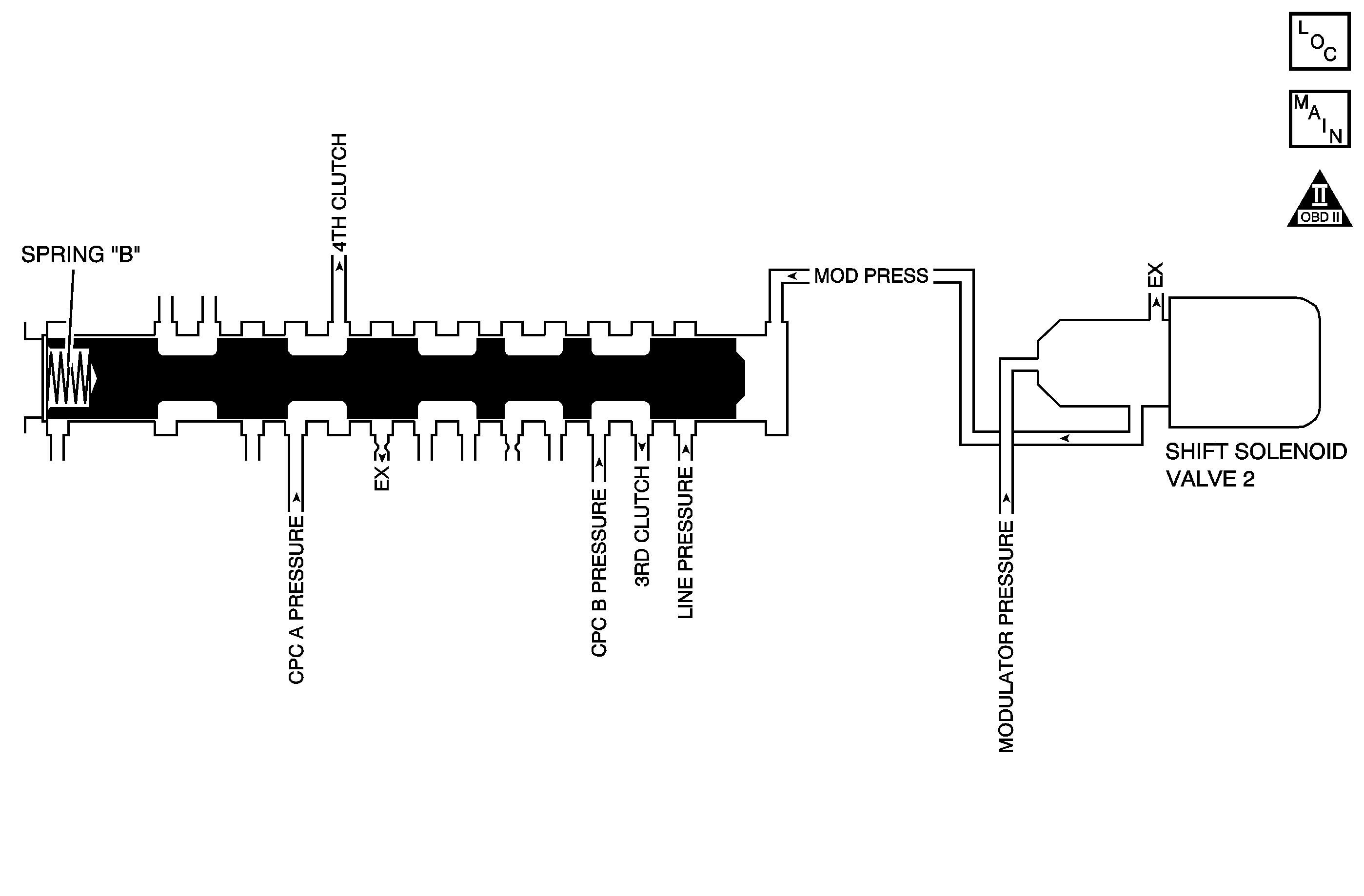
Circuit Description
The shift solenoid (SS) valve 2 is mounted to the transmission case and is used to supply or limit the modulated pressure to the shift valve B, according to the PCM command. The powertrain control module (PCM) provides an output signal to SS valve 2, which supplies clutch control pressure to the clutch of an appropriate gear position, as determined by the shift schedule. When the PCM commands the shift solenoid 2 ON, the modulated pressure is not supplied to the shift valve B, and the shift valve B is pushed by the reactive force of spring B. When the PCM command is OFF, the modulated pressure is supplied to the valve. The PCM monitors mainshaft to output shaft speed ratio in the gear positions determined by the shift schedule.
When the PCM detects an incorrect ratio for the commanded gear, DTC P0757 sets. DTC P0757 is a type B DTC.
Refer to Shift Solenoid Valve State and Gear Ratio .
DTC Descriptor
This diagnostic procedure supports the following DTC:
DTC P0757 2-3 Shift Solenoid (SS) Valve Performance - No Third, Fourth or Fifth Gear
Conditions for Running the DTC
| • | No TP DTCs P0122, P0123, P0222, or P0223. |
| • | No VSS DTCs P0501, P0502, or P0503. |
| • | No TR Switch DTC P0705. |
| • | No AT ISS DTCs P0716, P0717, or P0718. |
| • | No Clutch PC Solenoid 1 DTC P0746 or P0747. |
| • | No SS Valve Performance DTCs P0751, P0752, P0756, P0761, or P0762. |
| • | No Clutch PC Solenoid 2 P0776 or P0777. |
| • | No Incorrect Shift Pattern DTC P0780. |
| • | No Clutch PC Solenoid Electrical DTCs P0962 or P0963. |
| • | No Clutch PC Solenoid 2 DTCs P0966 or P0967. |
| • | No SS 1 DTCs P0973 or P0974. |
| • | No SS 2 DTCs P0976 or P0977. |
| • | No SS 3 DTCs P0979 or P0980. |
| • | No TAC DTCs P2101, P2108, P2111, P2112, or P2553. |
| • | No APP DTC P2122, P2123, P2127, P2128, P2135, or P2138. |
| • | No Minimum Idle Position DTC P2176. |
| • | No TCC PC Solenoid DTCs P2763 or P2764. |
| • | No TCC Enable Solenoid DTCs P2769 or P2770. |
| • | No TAC Communication DTC U0107. |
| • | System voltage is greater than 11 volts. |
| • | The TFT is greater than -25°C (-13°F). |
| • | Start the engine and drive so that the transmission shifts from 1st to 5th gear. |
Conditions for Setting the DTC
The gear remains in 3rd, in response to a 3-4 upshift command, when there is no history indicating a short shift time at a preceding 2-3 and 4-5 upshift operation.
Action Taken When the DTC Sets
| • | The PCM illuminates the malfunction indicator lamp (MIL) during the second consecutive trip in which the Conditions for Setting the DTC are met. |
| • | The PCM limits the transmission shift to 1st, 2nd and 3rd gear. |
| • | The PCM records the operating conditions when the Conditions for Setting the DTC are met. The PCM stores this information as Freeze Frame and Failure Records. |
| • | The PCM stores DTC P0757 in PCM history. |
Conditions for Clearing the MIL/DTC
| • | The PCM turns OFF the MIL during the third consecutive trip in which the diagnostic test runs and passes. |
| • | A scan tool can clear the MIL/DTC. |
| • | The PCM clears the DTC from PCM history if the vehicle completes 40 warm-up cycles without an emission related diagnostic fault occurring. |
| • | The PCM cancels the DTC default actions when the ignition switch is OFF long enough in order to power down the PCM. |
Diagnostic Aids
| • | Inspect for a stuck ON SS 2. |
| • | Inspect for a stuck shift valve B. |
Test Description
The numbers below refer to the step numbers on the diagnostic table.
-
This step inspects the transmission fluid to ensure that it is at the proper level.
-
During the SS valve 2 operation, listen for an audible click. Command the ON and the OFF states. Repeat the commands as necessary.
Step | Action | Yes | No | ||||||||||
|---|---|---|---|---|---|---|---|---|---|---|---|---|---|
1 | Did you perform the Diagnostic System Check - Vehicle? | Go to Step 2 | |||||||||||
Did you perform the Transmission Fluid Checking Procedure? | Go to Step 3 | Go to Transmission Fluid Check | |||||||||||
3 |
Important: Before clearing the DTC, use the scan tool in order to record the Freeze Frame and Failure Records. Using the Clear Info function erases the Freeze Frame and Failure Records from the PCM. Does the DTC reset? | Go to Step 4 | Go to Diagnostic Aids | ||||||||||
Does the SS valve 2 click with each command? | Go to Step 5 | Go to Step 6 | |||||||||||
5 |
Did you complete the repair? | Go to Step 7 | -- | ||||||||||
6 | Replace the SS valve 2. Refer to Accumulator Valve Body Assembly Overhaul . Did you complete the replacement? | Go to Step 7 | -- | ||||||||||
7 | Perform the following procedure in order to verify the repair:
Has the test run and passed? | Go to Step 8 | Go to Step 2 | ||||||||||
8 | With the scan tool, observe the stored information, capture info and DTC info. Does the scan tool display any DTCs that you have not diagnosed? | System OK |
