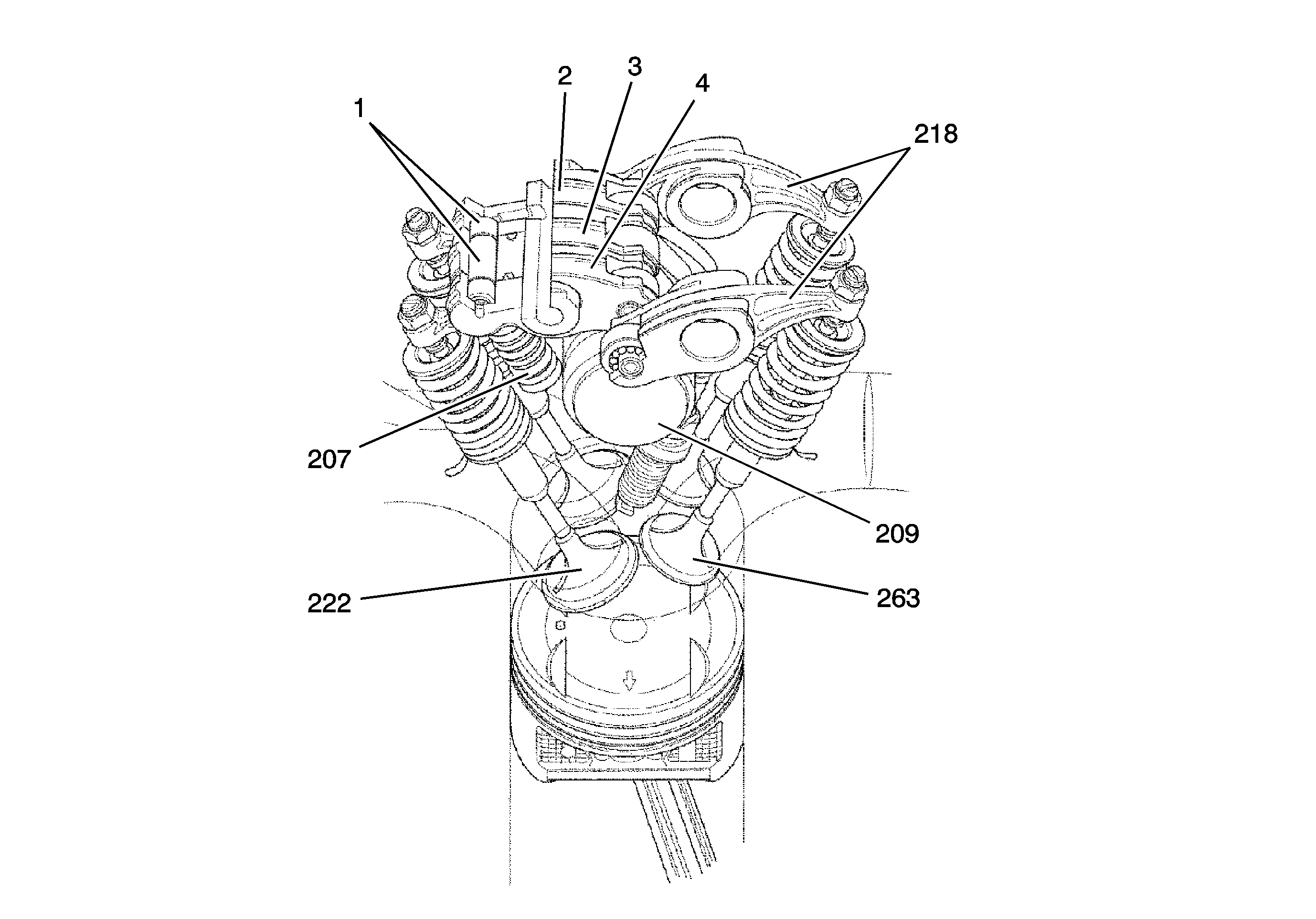
The intake rocker arm control system is designed to change valve timing and lift, depending on engine speed, vehicle speed, engine load, and other sensor inputs, by controlling intake valve rocker arm actuation. The intake rocker arm control system achieves low-end torque and low fuel consumption when operating in the low engine speed range, while maintaining high power output when operating in the high engine speed range. The engine has a normal 4 valve per cylinder arrangement. At low engine speed, the primary (4) and secondary (2) intake valve rocker arms operate at normal lift. At high engine speed, the primary (4) and secondary (2) intake rocker arms are mechanically connected to the mid intake rocker arm (3) to allow high valve lift. Synchronizing pistons (1) connect and disconnect the 3 intake rocker arms. Hydraulic pressure against a timing piston moves the synchronizing piston outward. A stopper piston and return spring move the synchronizing piston back or inward when hydraulic pressure is reduced.
The system consists of the following components:
| • | A spool valve assembly with solenoid |
| • | An oil pressure switch |
| • | Valve lash adjusters-lost motion assemblies |
| • | An intake rocker arm assembly with moving-internal pistons |
Low Speed Operation
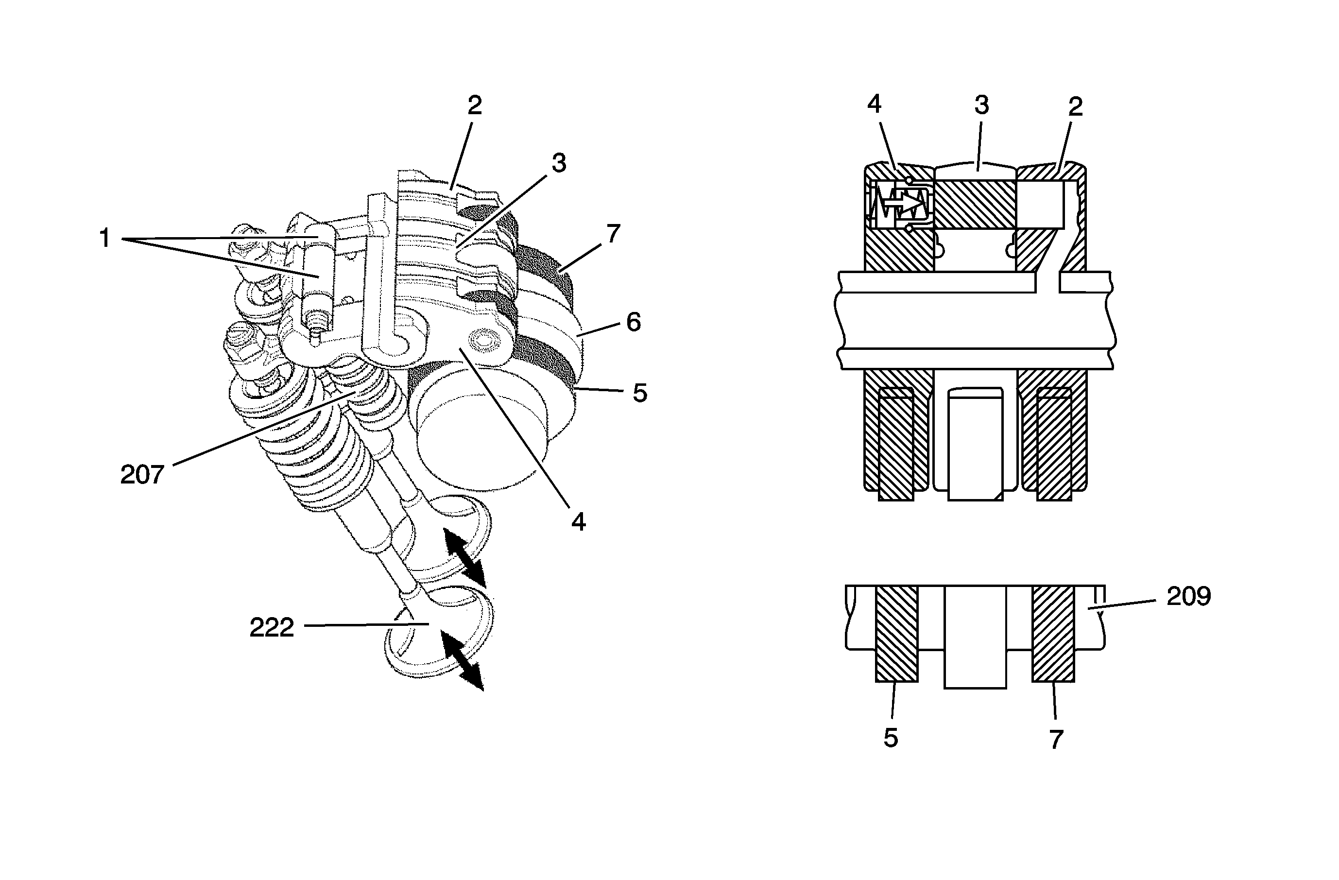
The primary (4) and secondary (2) rocker arms are not connected to the mid rocker arm (3) and are driven separately by the camshaft lobes (5 and 7). Even though the mid rocker arm (3) is following the center camshaft lobe (6), it has no effect on the opening and closing of the valves in the low RPM range. The valve lash adjuster (207) absorbs the lost motion action of the mid rocker arm.
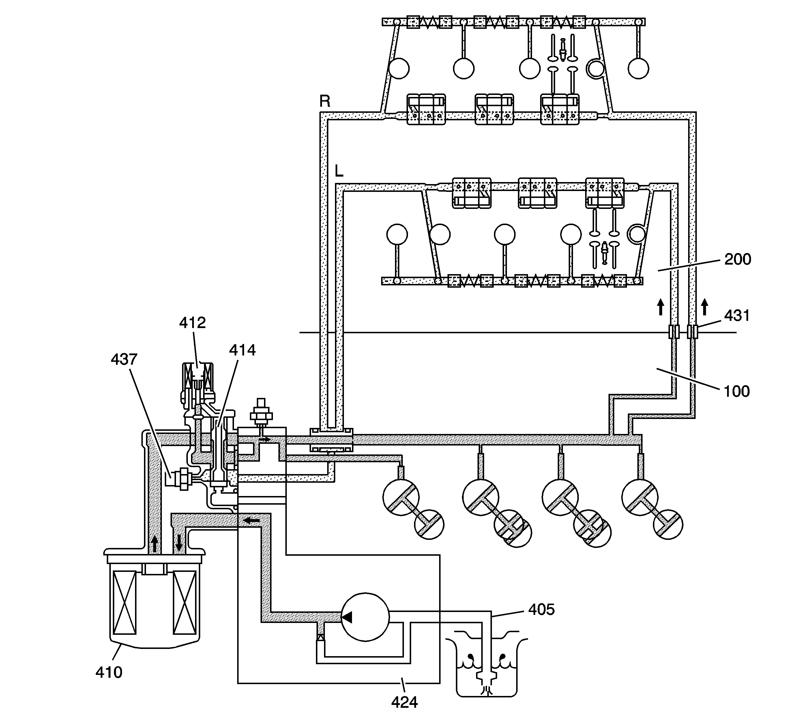
The oil is pulled from the oil sump through the screen (405). Oil pressure generated in the oil pump (424) is supplied through the oil filter (410) to the engine block (100). The oil pressure is then directed to the cylinder heads (200) for rocker arm and camshaft lubrication. The oil restrictors (431) located within the upper engine block reduce the oil pressure to eliminate intake rocker arm piston actuation.
High Speed Operation
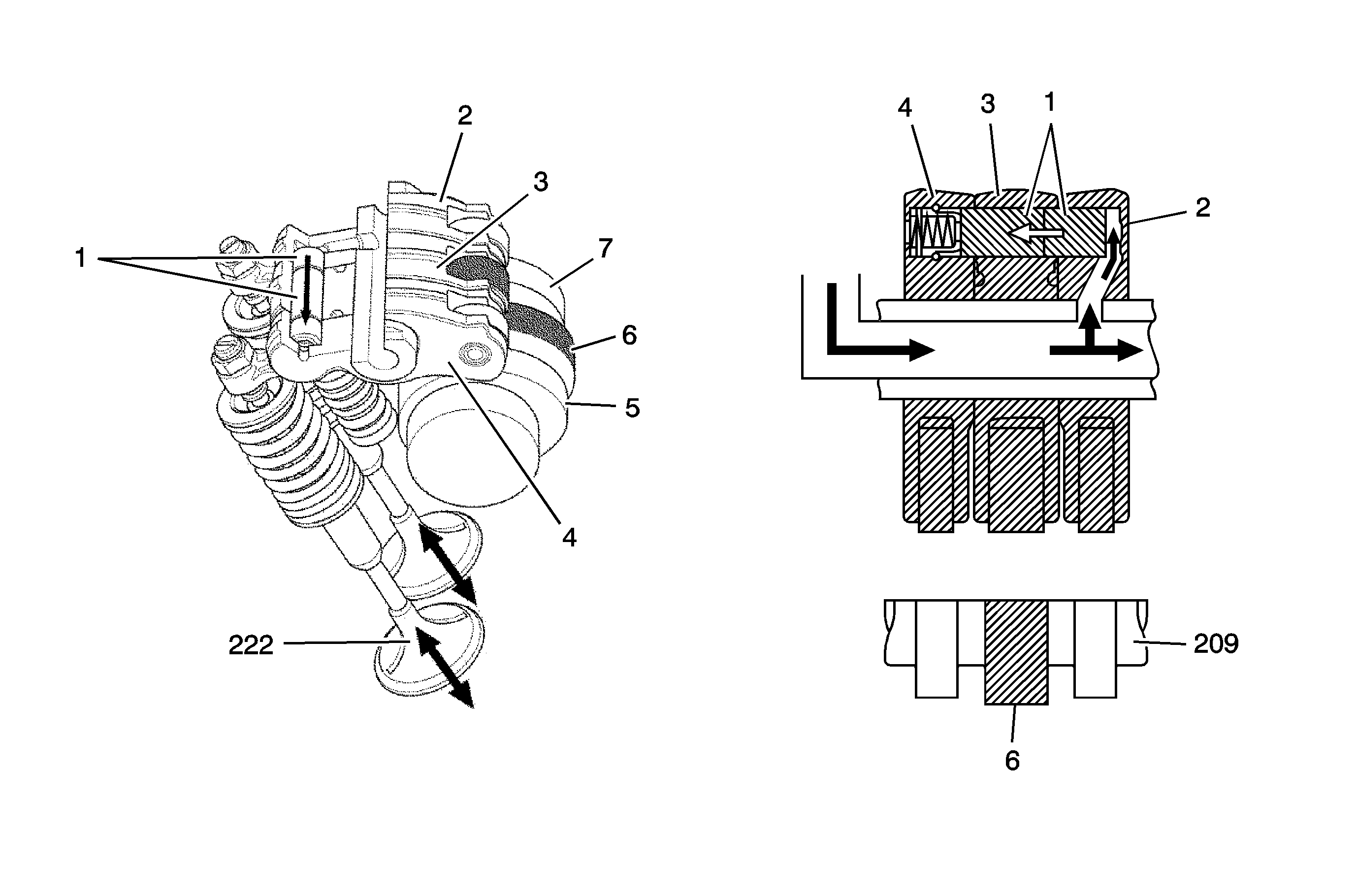
The synchronizing pistons (1) move in the direction, as indicated, to mechanically connect the primary (4), secondary (2), and mid (3) rocker arms. The 3 rocker arms move as a single unit and are driven by the high range camshaft lobe (6). In this mode of operation, the valve timing and lift are set for high speed operation.
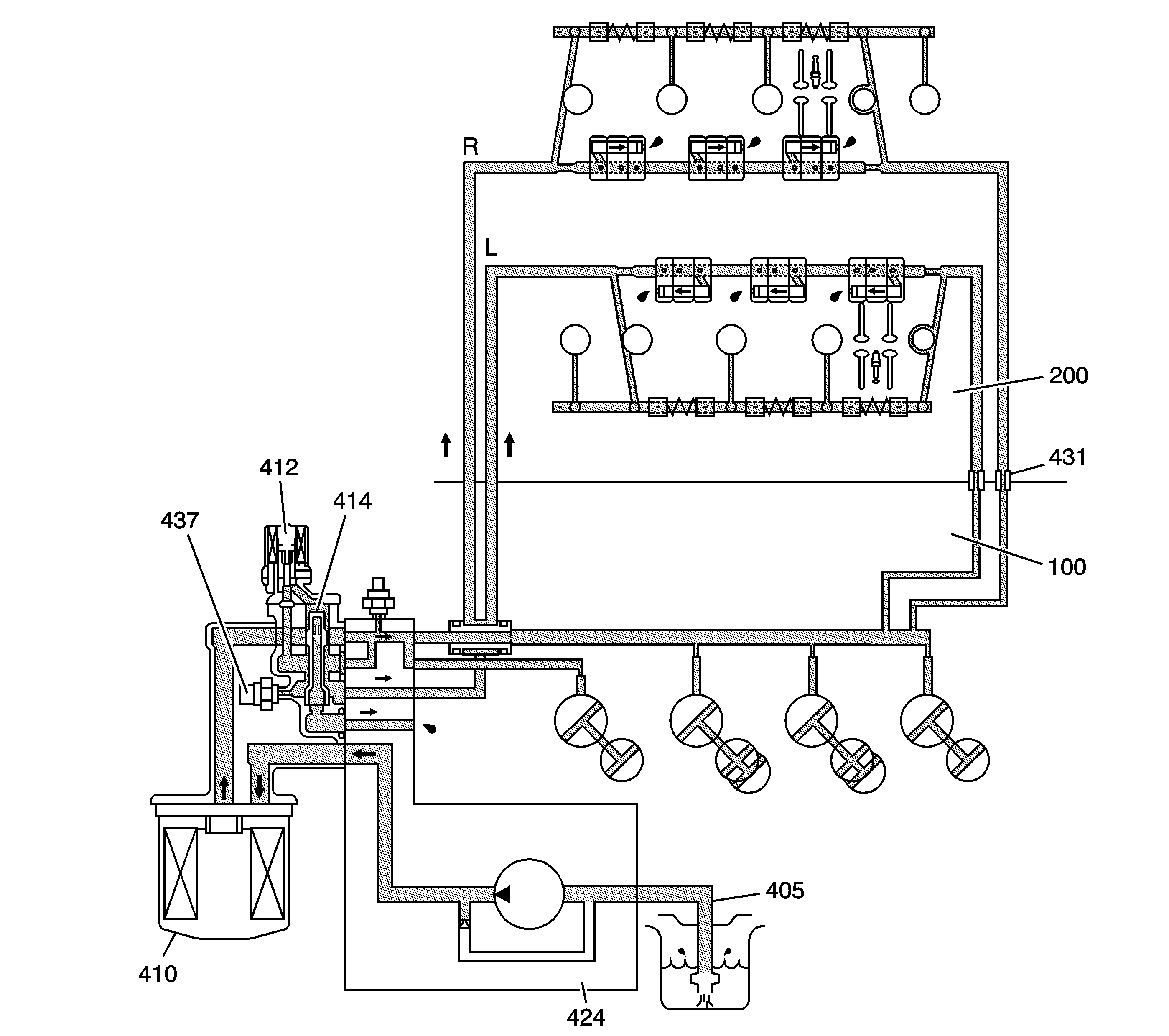
The oil is pulled from the oil sump through the screen (405). Oil pressure is generated in the oil pump (424) and is supplied through the oil filter (410) to the oil flow control module. The solenoid valve (412) is energized, moving the spool valve (414). Increased oil pressure is then supplied to the synchronizing pistons, which move to connect the primary, secondary, and mid rocker arms.
Valve Lash Adjuster
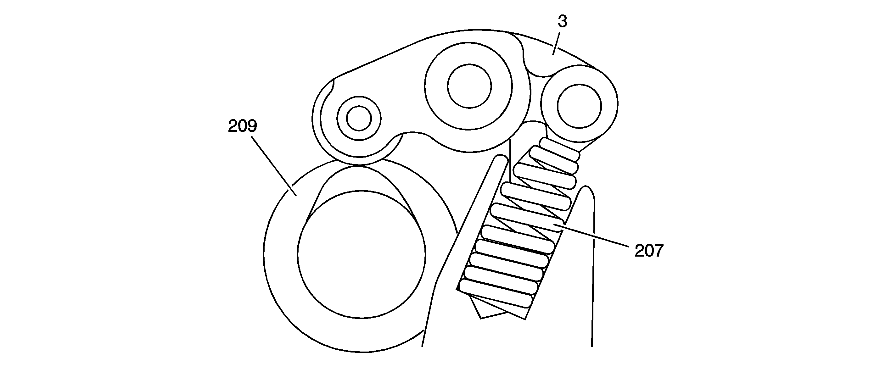
The lash adjuster, or lost motion assembly (207), includes a spring and retainer. The lash adjuster is in constant contact with the mid (3) rocker arm. At low speeds, the lash adjuster suppresses unnecessary movement of the mid rocker arm. The lash adjuster functions as an auxiliary spring at high speeds to ensure smooth valve operation.
Electrical System Components
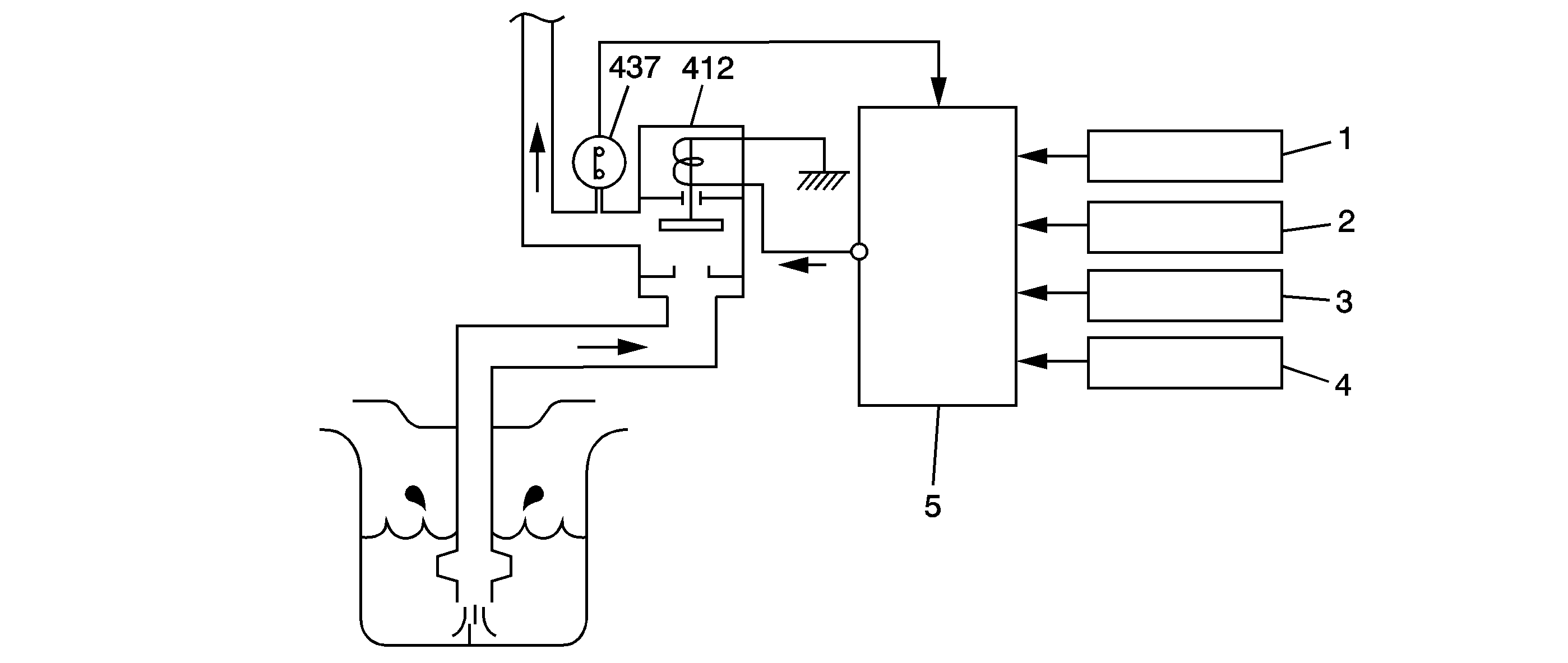
The PCM (5) constantly monitors the changes in engine status, such as engine speed (1), engine load (2), vehicle speed (3), and coolant temperature (4). The PCM directs the oil flow control module (412) to provide higher oil pressure to the intake valve rocker arms as required. The oil pressure switch (437) provides a signal to the PCM that oil pressure is present.
The following criteria is required for intake rocker arm activation:
| • | Engine speed of 4,400 RPM or greater |
| • | Engine coolant temperature (ECT) sensor reading of 10°C (50°F) or greater |
| • | Battery voltage of 10.5 volts or greater |
| • | Transmission shift lever in a position other than P or N |
| • | Engine has been running for longer than 5 seconds |
| • | Additional information can be found within engine controls information. Refer to Rocker Arm Oil Control System Description . |
Spool Valve and Oil Pressure Switch
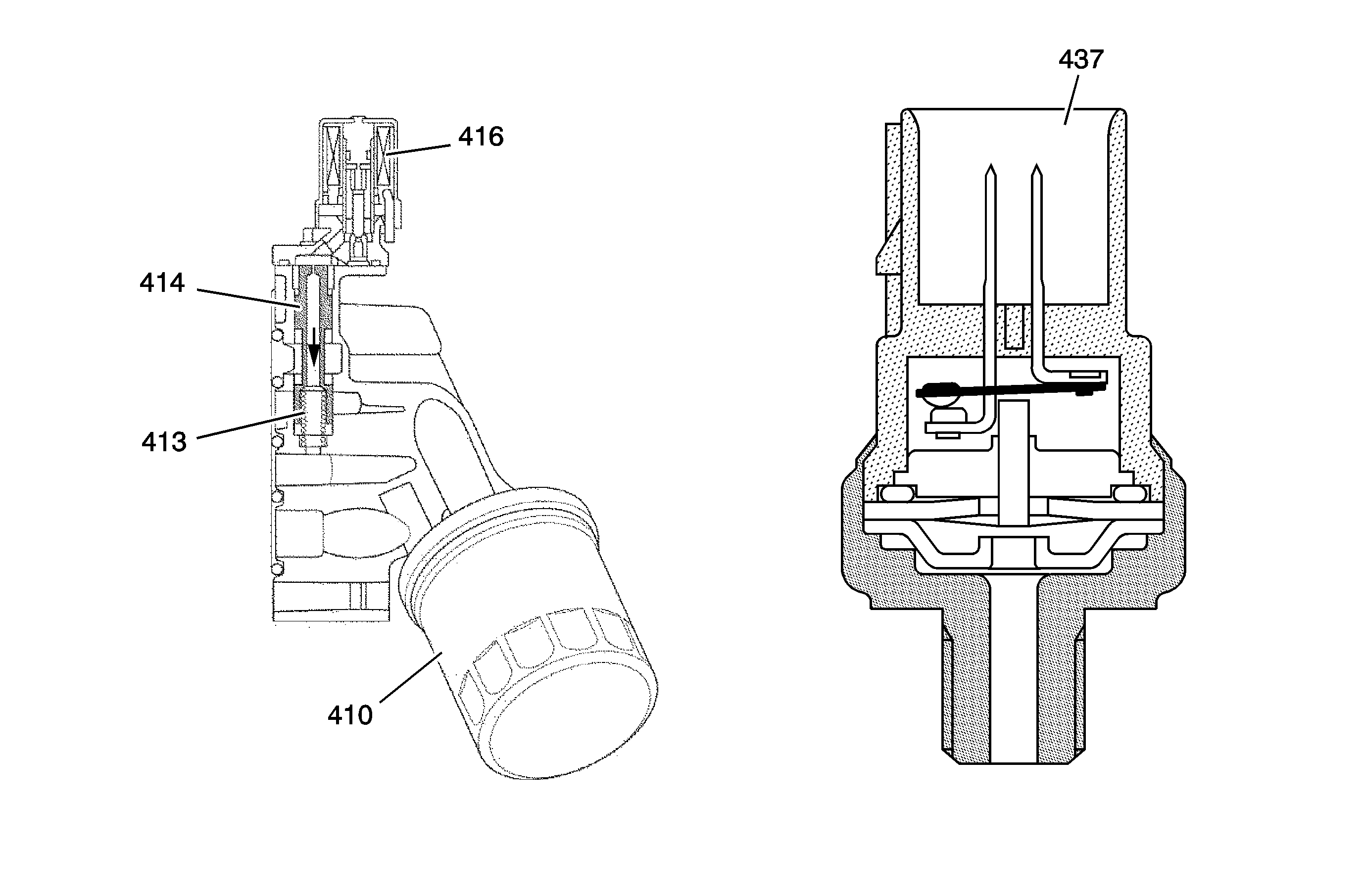
The spool valve assembly, or oil flow control module, is mounted to the front right of the engine block at the oil pump housing. The module consists of an oil filter (410), solenoid (416), spool valve (414) and spring (413). The module controls oil flow between the oil pump and the synchronizing pistons of the intake rocker arms. When the solenoid is activated, the oil pressure pushes the spool valve downward. The spool valve then opens the oil passage, and hydraulic pressure is applied to the synchronizing pistons, thus activating the intake rocker arm control system. The oil pressure sensor (437) is located on the housing by the solenoid valve and is in a normally closed position. The switch is used to detect oil pressure and to activate the intake rocker arm control system. The PCM provides 5 volts to the switch, the switch opens through the body, the solenoid is energized, and oil pressure applied.
