Removal Procedure
Important: The park lock cable clips and park lock cable end fittings are one time usage
only. Any service repair requiring the park lock cable to be disconnected from the
ignition module or shift control will require replacement of the cable clip and/or
cable end fitting.
- Disable the SIR system. Refer to
SIR Disabling and Enabling
in SIR.
- Remove the left console trim panel. Refer to
Front Floor Console Side Trim Panel Replacement - Left Side
in Instrument Panel, Gages and Console.
- Remove the lock cylinder bezel from the steering column shroud by carefully
prying with a thin bladed screwdriver.
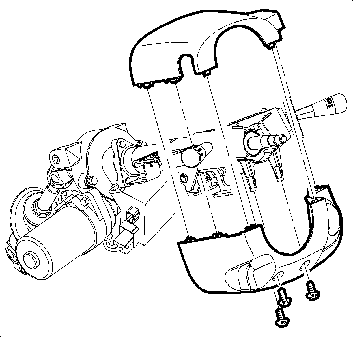
- Remove
the shroud fasteners and remove the steering column upper and lower shroud panels.
- Make sure the key is in the OFF position.
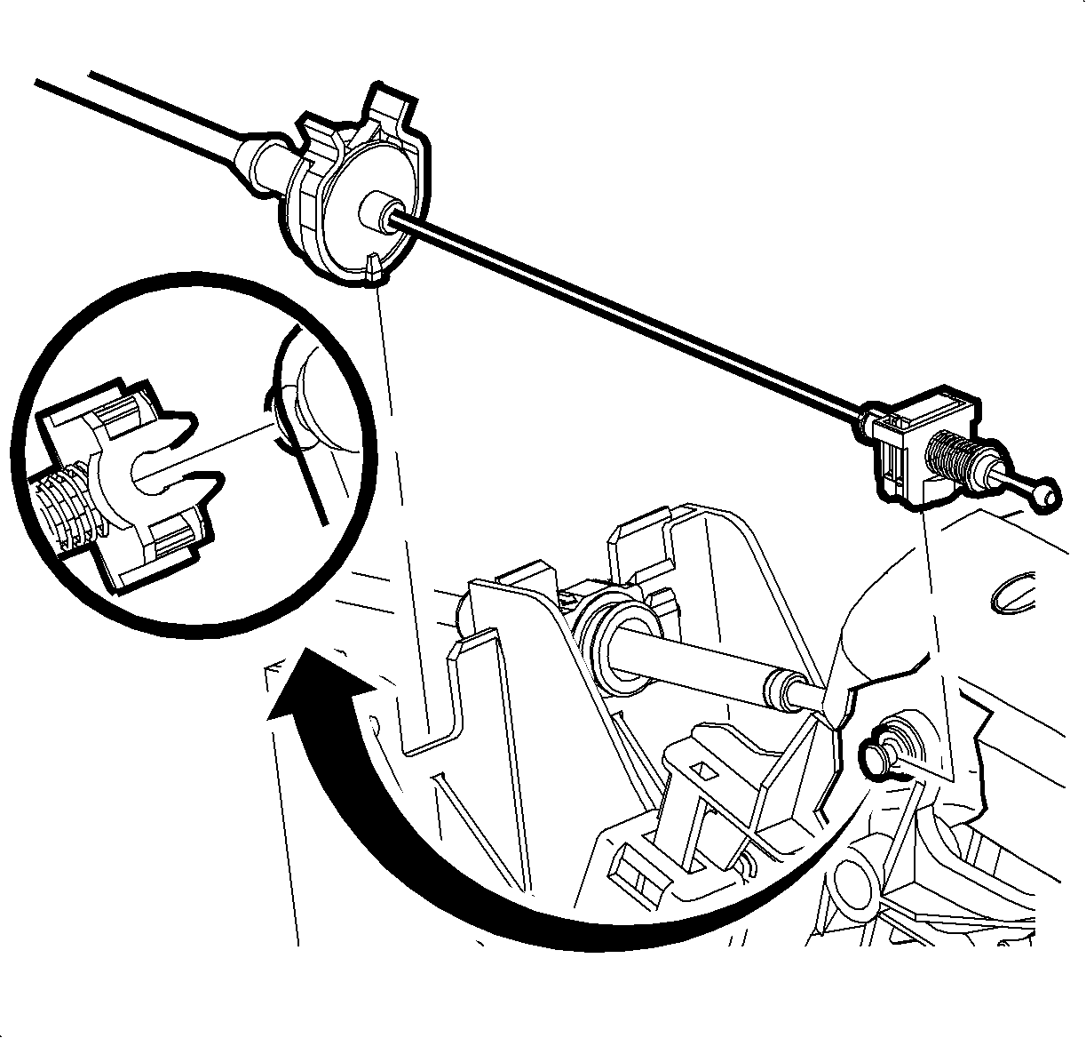
- Squeeze the tabs on the park lock cable
clip and pull upward to remove the cable from the shift control. Discard the park
lock cable clip.
- Disconnect the park lock cable from the shift control park lock lever.
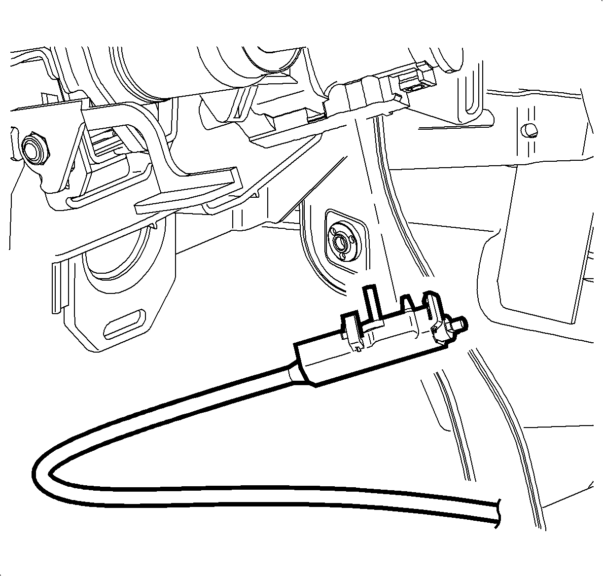
- Disengage the retaining tabs and remove
the park lock cable from the ignition module.
- Note the park lock cable routing while removing the park lock cable from
the vehicle.
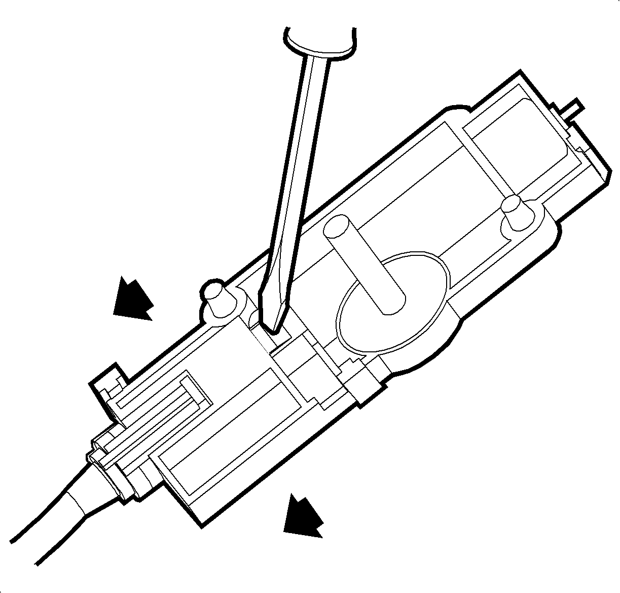
- Using a screwdriver, push on the black tab
to release the end fitting. Discard the end fitting.
Installation Procedure

- Install a new end fitting on the park lock
cable.

- Install the park lock cable onto the ignition
module.

- Install the park lock cable onto the shift
control , using a new clip.
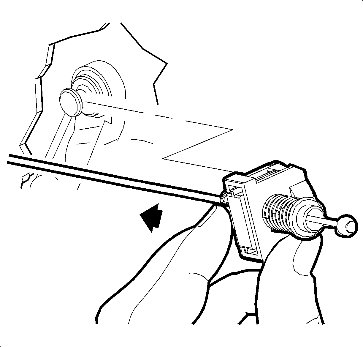
- Install the park lock cable end terminal
onto the park lock lever by aligning the cable fitting to the park lock lever pin
and pushing forward. When installing, be sure not to install the cable end fitting
on an angle or push down on the cable portion as this may cause cable to misadjust.
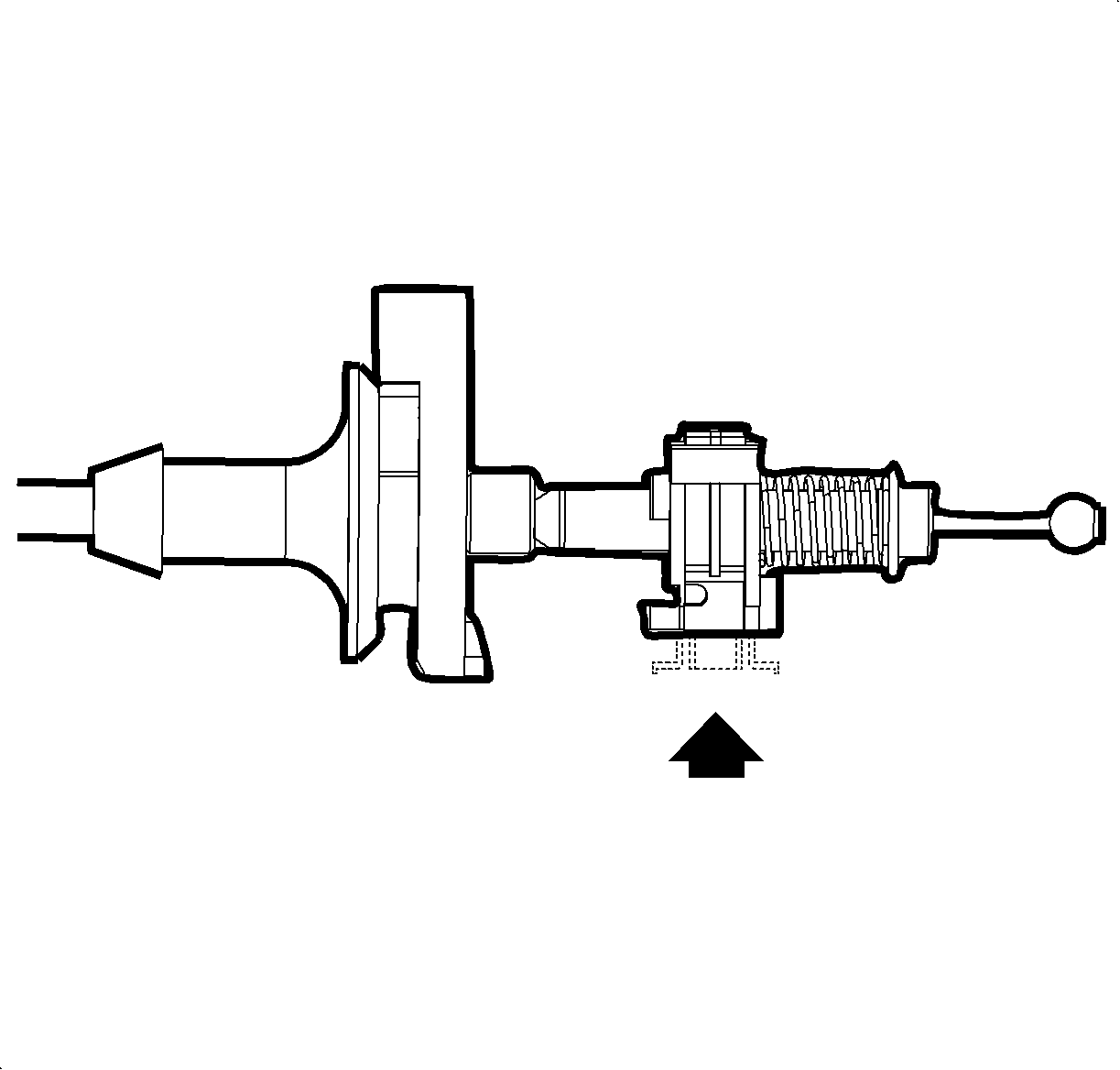
- With the cable adjuster in the unlocked
position, verify the shift control is in the park (P) position. Lock the adjuster
piece into place by pushing in on the tab, then check the cable adjustment as follows:
| 5.1. | Set the parking brake. |
| 5.2. | With the ignition key removed from ignition lock cylinder and control
shift lever in the park (P) position, depress the control shift lever button
and attempt to move control shift lever out of park (P) position. |
| • | If control shift lever can be shifted out of park (P) position,
perform step 5 over again ensuring that the cable adjuster lock is operating
properly. |
| • | If control shift lever cannot be shifted out of park (P) position,
proceed to next step. |
| 5.3. | Insert the ignition key into the ignition lock cylinder assembly and turn
to RUN position. |
| 5.4. | Depress the brake pedal and depress the control shift lever button and
move control shift lever out of park (P) position. |
| 5.5. | Release the brake pedal. With the control shift lever out of the park (P)
position, attempt to turn ignition to LOCK position. Ensure the ignition key is pushed
inward toward the steering column when it is rotated toward LOCK position. |
| • | If ignition key can be turned to LOCK position with control shift lever
out of park (P) position, return to the beginning of step 5 and check
the park lock cable adjustment. |
| • | If the ignition key cannot be turned to LOCK position with the control
shift lever out of the park (P) position, park lock cable is properly adjusted.
Proceed to next step. |
| 5.6. | Depress the control shift lever button. Move control shift lever to park (P)
position. |
| 5.7. | Turn the ignition key to ON position and then to OFF position. |
| 5.8. | Ensure ignition key is removable. |
| • | If ignition key can be removed from ignition lock cylinder assembly, proceed
to next step. |
| • | If ignition key cannot be removed from ignition lock assembly, return
to the beginning of step 5 and check the park lock cable adjustment. |
| 5.9. | Turn the ignition key to LOCK position. |
| 5.10. | Remove the ignition key from the ignition lock cylinder assembly. |

- Install
the shroud fasteners and install the steering column upper and lower shroud panels.
- Install the lock cylinder bezel onto the steering column shroud.
- Install the left console trim panel. Refer to
Front Floor Console Side Trim Panel Replacement - Left Side
in Instrument Panel, Gages and Console.
- Enable the SIR system. Refer to
SIR Disabling and Enabling
in SIR.


