For 1990-2009 cars only
Removal Procedure
- Remove the SIR module. Refer to Inflatable Restraint Steering Wheel Module Replacement in SIR.
- Remove the steering wheel. Refer to Steering Wheel Replacement .
- Remove the SIR coil. Refer to Inflatable Restraint Steering Wheel Module Coil Replacement in SIR.
- Using a thin-bladed screwdriver, remove the lock cylinder bezel.
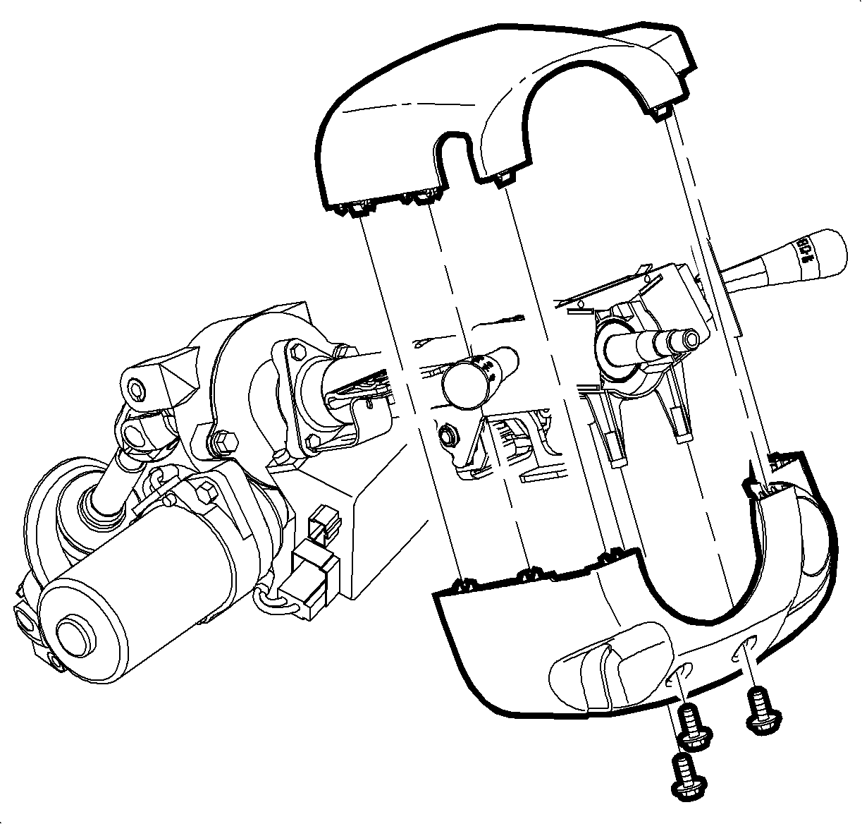
- Remove the shroud fasteners.
- Remove the upper and lower shrouds.
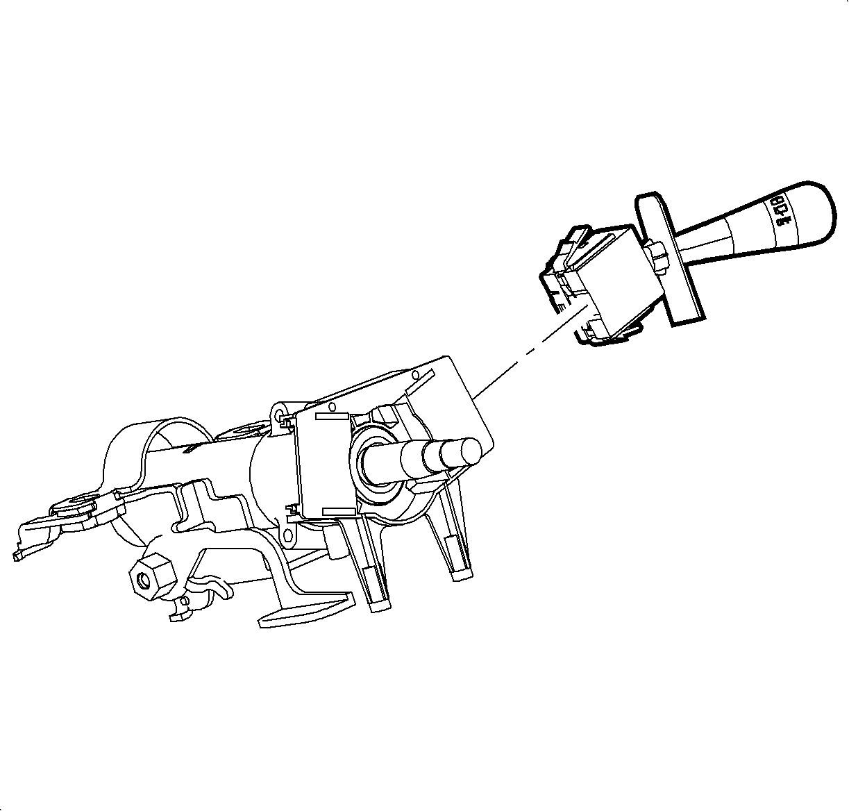
- Depress the lock tabs on the left and right multi-function levers. Remove the multi-function levers.
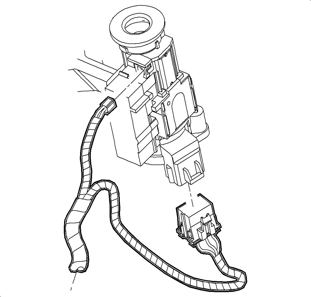
- Disconnect the electrical housing electrical connectors.
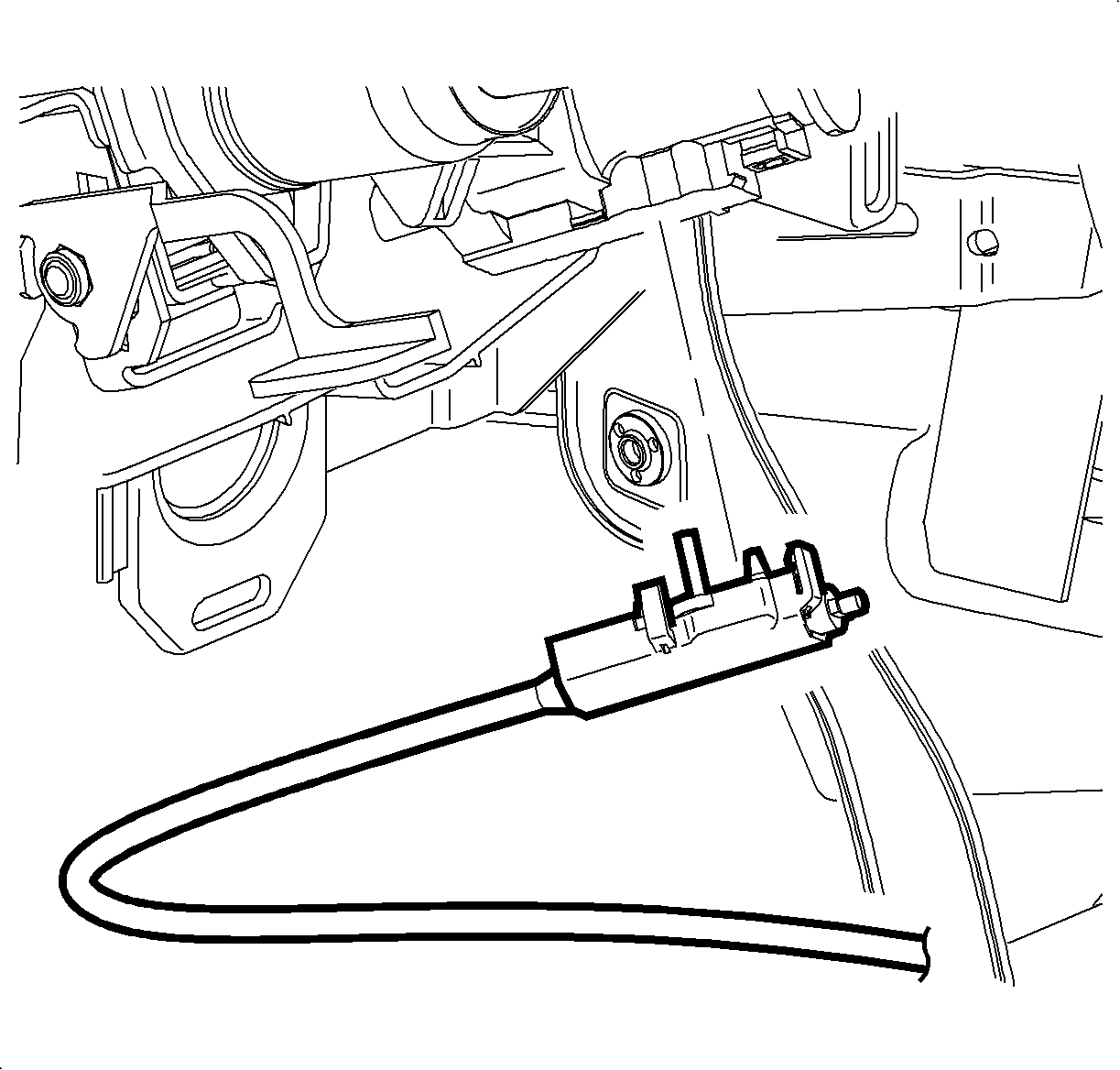
- Disengage the retaining tabs on the park lock cable assembly. Remove the assembly from the ignition module.
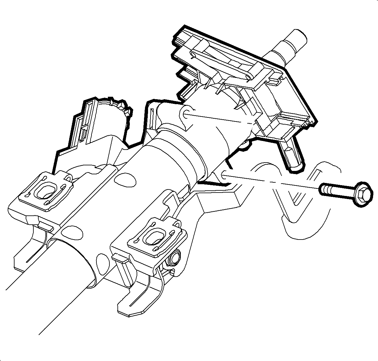
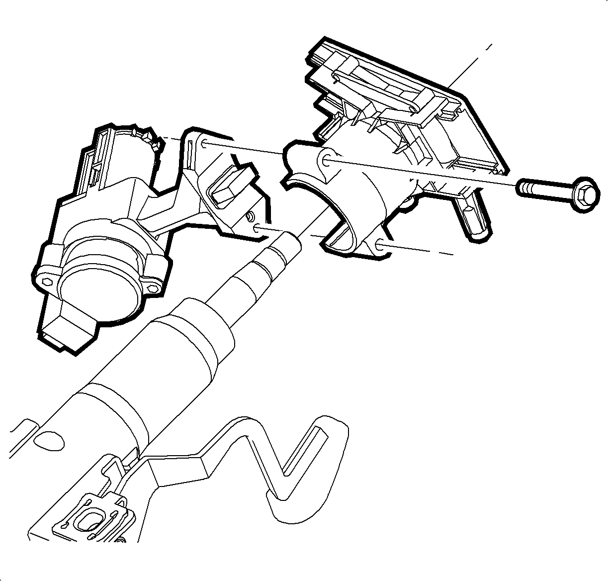
- Remove the lock housing bolts.
- Turn the ignition key to the ACC position
- Separate the ignition housing from the multi-function bracket.
- Remove the ignition switch screws
- Remove the ignition switch.
Installation Procedure
- Ensure that the ignition switch is in the ACC position.
- Position the ignition switch to the housing. Tighten the screws until seated.
- Pre-assemble the lock housing and multi-function lever bracket. Hand-tighten the bolts, leaving approximately 3.2 mm (0.125 in) gap at the bolt ends.
- Slide the bracket onto the column.
- Hand tighten the lower bolt until snug.
- Hand tighten the upper bolt until snug.
- Tighten the lower bolt.
- Tighten the upper bolt.
- Snap the ignition lock cable onto the ignition module.
- Connect the ignition switch electrical connector
- Connect the ignition housing electrical connectors.
- Install the multi-function levers.
- Install the upper and lower shrouds.
- Install the lock cylinder bezel.
- Install the SIR coil. Refer to Inflatable Restraint Steering Wheel Module Coil Replacement in SIR.
- Install the steering wheel. Refer to Steering Wheel Replacement .
- Install the SIR module. Refer to Inflatable Restraint Steering Wheel Module Replacement in SIR.

Notice: Refer to Fastener Notice in the Preface section.
Tighten
Tighten the ignition screws to 2.5 N·m (22 lb in).
Important: Ensure that the lock tab fully engages into the column slot.

Tighten
Tighten the bolt to 8 N·m (71 lb in)
Tighten
Tighten the bolt to 8 N·m (71 lb in)


Important: Ensure that both locking tabs are seated.

Tighten
Tighten the shroud screws to 2 N·m (18 lb in)
