GM Service Manual Online
For 1990-2009 cars only

Object Number: 1251001  Size: MH

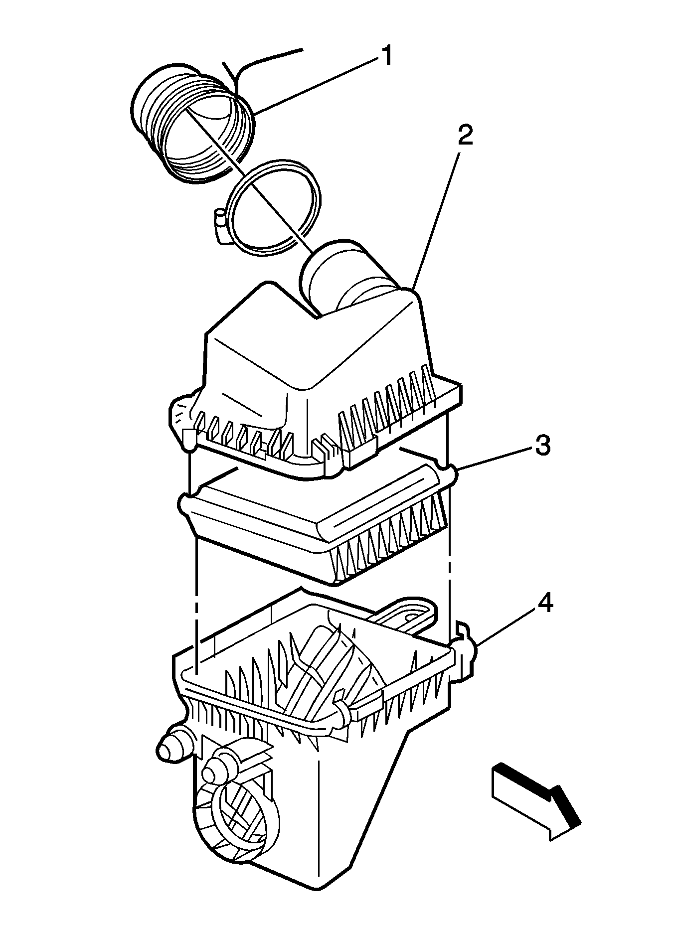
The air induction system provides air with oxygen for the combustion process. The air cleaner keeps dirt from entering the engine. Outside air is drawn into the air cleaner lower assembly (4) and passes through the air cleaner element (3). Next the air enters the air cleaner upper assembly (2) and flows through the inlet air duct (1), to the throttle body, and into the intake manifold. Finally the air travels into the cylinder head and through the intake port, ending in the combustion chamber. The inlet air duct contains the intake air temperature (IAT) sensor 1.

The following components are directly or indirectly a part of the air supply system.
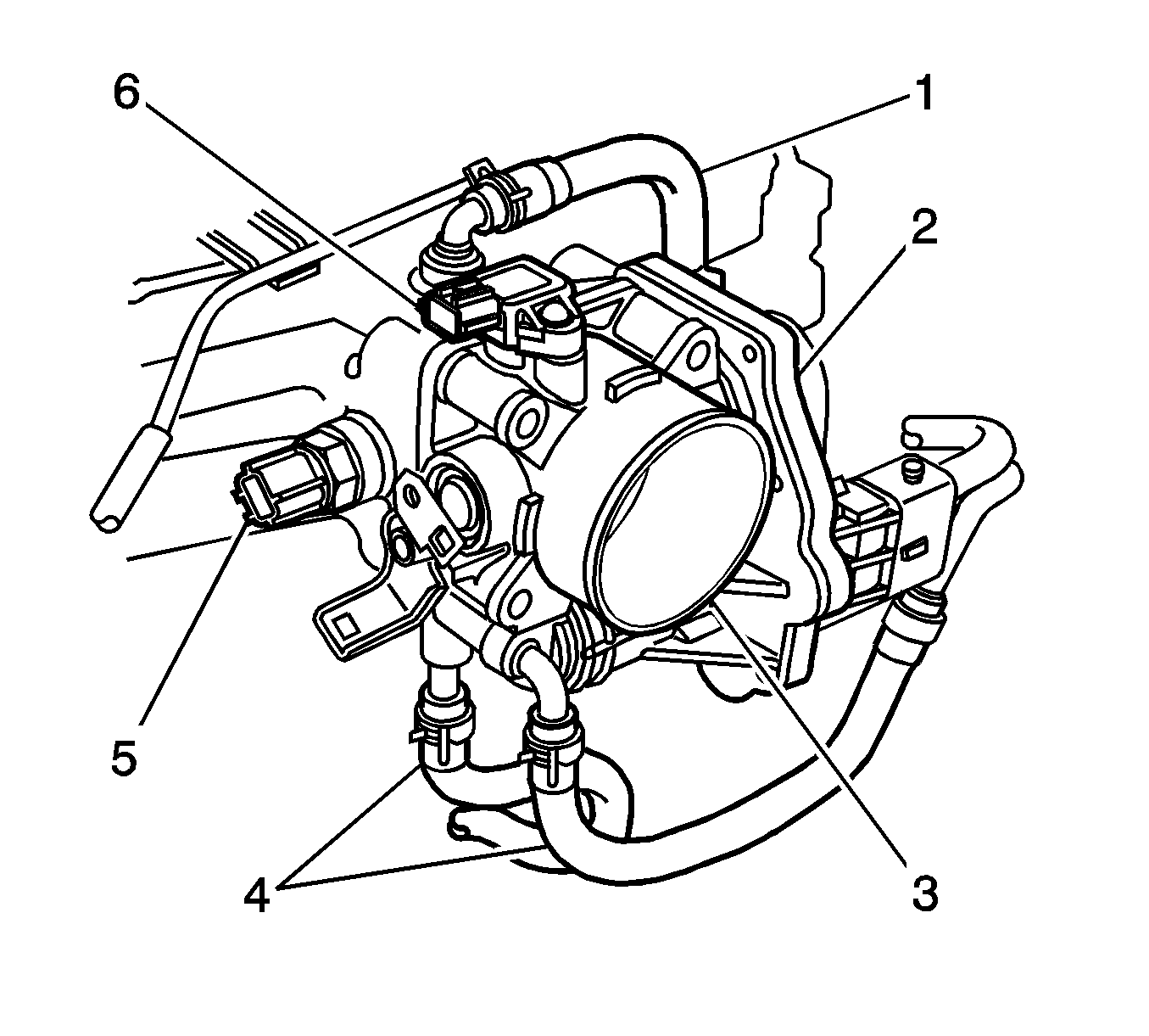
Throttle Body Assembly


Object Number: 1233528  Size: SH
(1)Positive Crankcase Ventilation (PCV) Hose
(2)Throttle Actuator Control (TAC) Module
(3)Throttle Body
(4)Engine Coolant Hoses
(5)Intake Air Temperature (IAT) Sensor 2
(6)Manifold Absolute Pressure (MAP) Sensor

The throttle body contains a throttle valve that controls the amount of air entering the engine. The throttle valve is opened and closed by the throttle actuator control (TAC) motor. The TAC motor is an integral part of the TAC module assembly (2) mounted on the side of the throttle body. The TAC motor is controlled by commands from the powertrain control module (PCM), passed to the module circuitry through a dedicated serial data line. The TAC module also contains two throttle position (TP) sensors, TP sensor 1 and TP sensor 2. For detailed information on the operation of the TAC system refer to Throttle Actuator Control (TAC) System Description .

In order to prevent cold weather icing and stabilize cold weather performance, the throttle body is warmed by engine coolant (4). The manifold absolute pressure (MAP) sensor (6) is located on top of throttle body.

Engine Idle Speed Control

The engine idle speed is controlled by the powertrain control module (PCM) through the throttle actuator control (TAC) motor located in the TAC module assembly. There are several reasons for idle speed control:

  1. In order to maintain the engine idle speed at the specified RPM at all times. The engine idle speed can vary due to any of the following reasons:
  2. • A change in the load applied to engine such as when the rear defogger is operating, the automatic transaxle is shifted to R, D, 2 or L ranges, the A/C is turned ON, the headlights or stop lights are turned ON, etc.
    • A change in the atmospheric pressure.
    • A change in the engine's condition over time.
  3. In order to improve the starting performance of the engine.
  4. In order to improve the driveability of the engine during warm up.
  5. In order to compensate for the change in the air/fuel mixture ratio when decelerating.

Intake Air Temperature (IAT) Sensors

The intake air temperature (IAT) sensor 1 is located in the inlet air duct between the air cleaner and the throttle body. The intake air temperature (IAT) sensor 2 is mounted in the front of the intake manifold just behind the throttle body. The IAT sensors measure the temperature of the air at their respective locations in the intake system. The IAT sensors provide useful air temperature information to the powertrain control module (PCM).

Each IAT sensor is a thermistor--a resistor whose resistance changes as a function of temperature. When the temperature is low, the resistance is high. The resistance decreases as the temperature increases. The IAT sensor is a 2-wire circuit with a reference or signal voltage and a ground coming from the PCM.

IAT Sensor Operation

Temperature

Resistance

Voltage

Low

High

High

High

Low

Low

Throttle Position (TP) Sensors

There are 2 throttle position (TP) sensors, both located in the molded side cover of the TAC module assembly. Each is a potentiometer connected to the throttle shaft of the throttle body. By monitoring the voltage on the signal line, the logic circuits in the throttle actuator control (TAC) module calculate the throttle position. When the TAC motor changes the throttle valve angle in response to accelerator pedal movement, the two TP sensor signal voltage outputs also change. Both TP sensor signal voltages are low at closed throttle and increase as the throttle opens. TP sensor 1 determines the actual throttle valve position. TP sensor 2 provides a backup value for TP sensor 1. For detailed information on the operation of the TAC system refer to Throttle Actuator Control (TAC) System Description .

Because the position of the throttle valve controls the air supply to the engine, the powertrain control module (PCM) will modify the fuel delivery based on the throttle angle. For example, power enrichment occurs when the throttle angle approaches wide-open throttle. The PCM looks primarily for changes in the manifold absolute pressure (MAP) sensor and TP sensor outputs in order to control fuel delivery.