Battery Tray Replacement 3.5L (L66)
Removal Procedure
- Remove the battery . Refer to Battery Replacement .
- Remove the 3 (UHJB) nuts and lift the UHJB from the battery tray.
- Remove the left headlight. Refer to Headlamp Assembly or Headlamp Bulb and/or Cornering, Sidemarker, Park, Turn Signal Bulb Replacement .
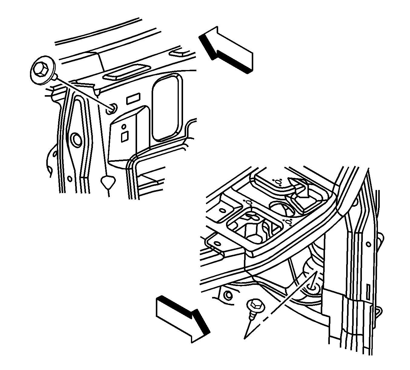
- Remove the battery tray bolt behind the headlight.
- Raise the vehicle. Refer to Lifting and Jacking the Vehicle .
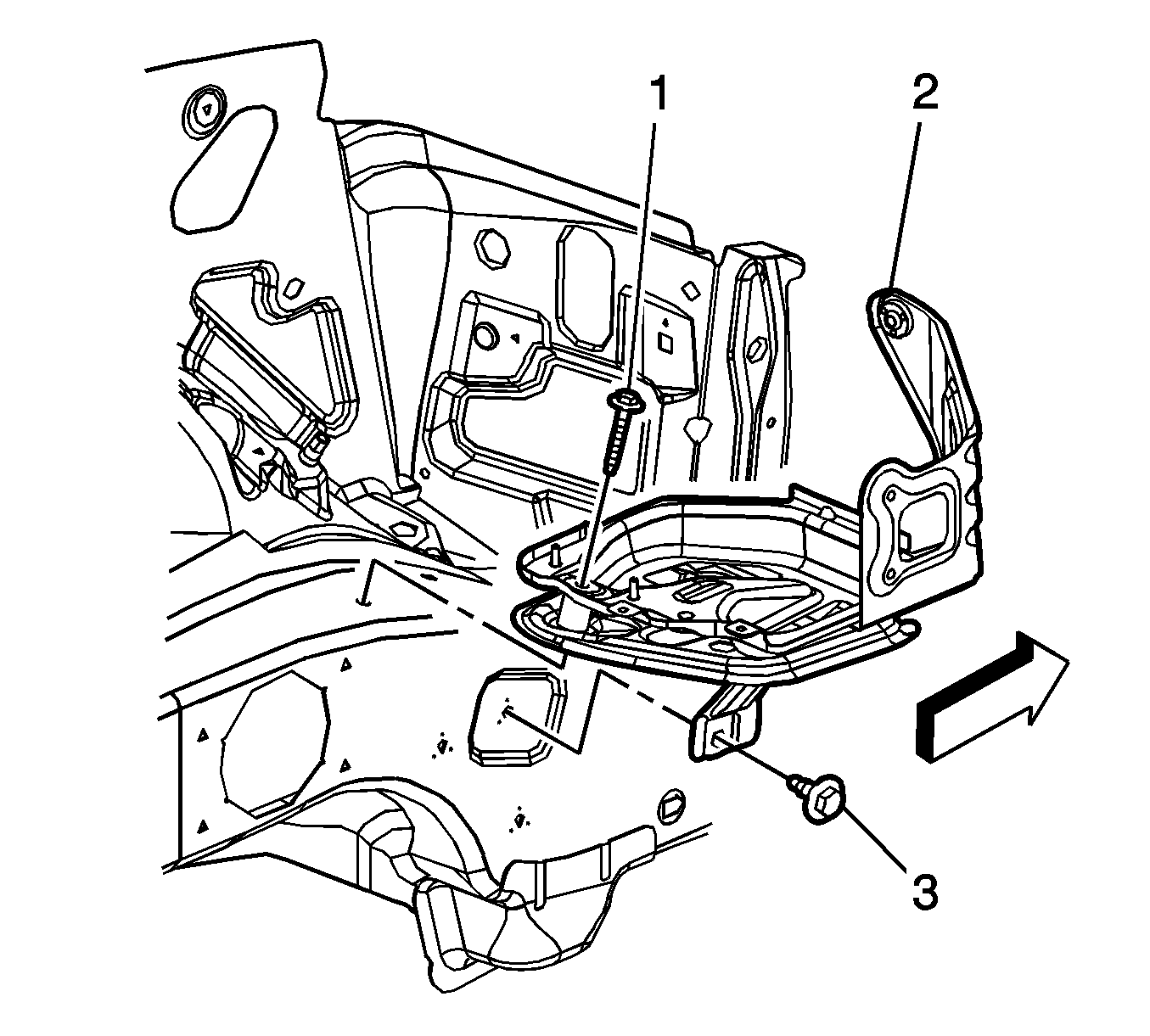
- Remove the lower battery tray bolt (3).
- Lower the vehicle.
- Remove the battery tray bolt on top of the side rail (1).
- Remove the battery tray.
Installation Procedure
- Position the battery tray bracket and install the bolt to the top of the side rail (1).
- Raise the vehicle. Refer to Lifting and Jacking the Vehicle .
- Install the lower battery tray bolt (3).
- Lower the vehicle.
- Install the battery tray bolt behind the headlight.
- Install the left headlight. Refer to Headlamp Assembly or Headlamp Bulb and/or Cornering, Sidemarker, Park, Turn Signal Bulb Replacement .
- Install the UHJB and nuts .
- Install the battery . Refer to Battery Replacement .
Notice: Refer to Fastener Notice in the Preface section.

Tighten
Tighten the battery tray bracket bolts to 15 N·m (11 lb ft).
Tighten
Tighten the battery tray bolt to 15 N·m (11 lb ft).

Tighten
Tighten the bolt to 15 N·m (11 lb ft).
Tighten
Tighten the nuts to 12 N·m (106 lb in).
Battery Tray Replacement 2.2L (L61)
Removal Procedure
- Turn the ignition OFF.
- Loosen the battery cover screws and remove the battery cover.
- Disconnect the negative battery cable. Refer to Battery Negative Cable Disconnection and Connection .
- Disconnect the positive battery cable.
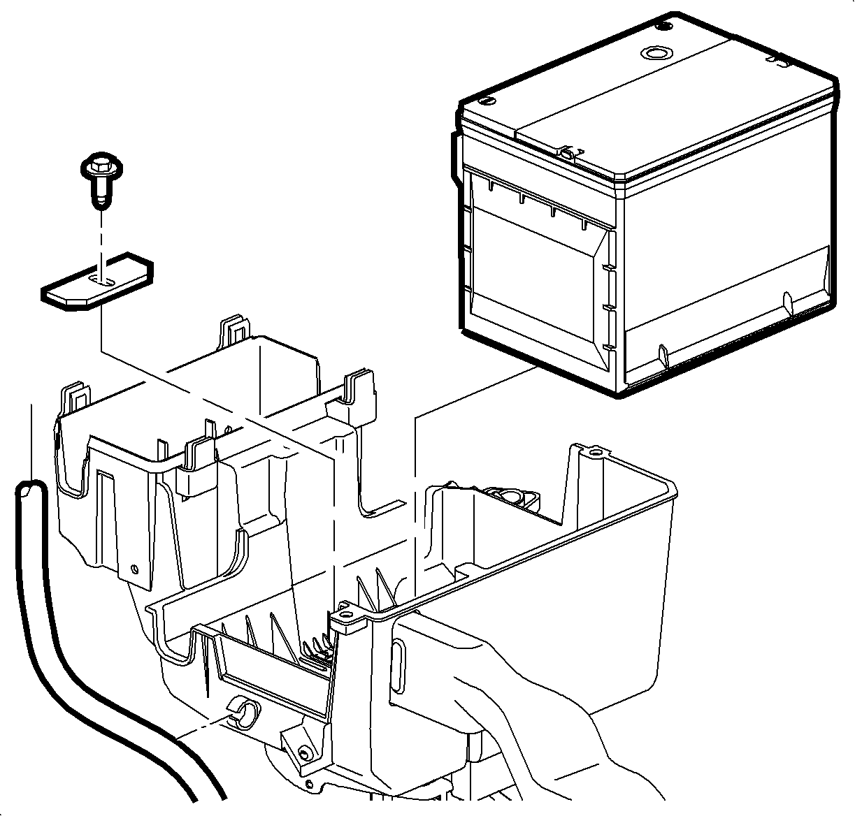
- Remove the battery hold down bolt and remove the battery.
- Remove the underhood fuse block (UHFB) cover.
- Remove the positive battery cable and electronic power steering (EPS) wire from B+ terminal at UHFB.
- Open all retainer clips and remove all cables, lines and harnesses from the battery cooling box.
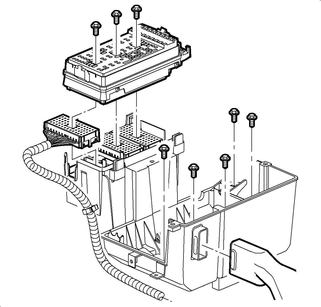
- Remove the UHFB connector retaining bolts.
- Unfasten the UHFB from its housing and disconnect the forward lamp harness.
- Remove the battery cooling box bolts.
- Remove the battery cooling box side support bolt.
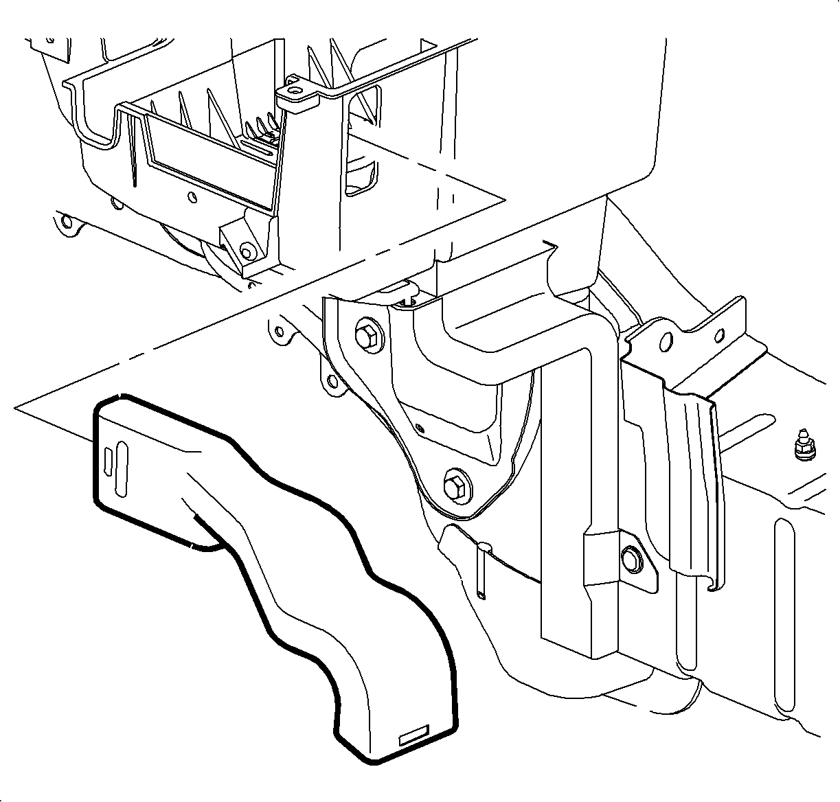
- Pull the inlet duct away from the battery cooling box.
- Rotate the UHFB out of the way and remove the battery cooling box.
Important: Record all pre-set radio stations.
Caution: Do not tip the battery over a 45 degree angle or acid could spill causing serious personal injury.
Important: Protect the disconnected harness from contamination during service.
Installation Procedure
- Position the battery cooling box on the tray so that the inlet and outlet ducts are properly aligned.
- Install the battery cooling box bolts.
- Install the battery cooling box side support bolt.
- Connect the forward lamp harness to the UHFB and attach the UHFB into the housing.
- Tighten the UHFB connector retaining screws.
- Secure all cables, lines and harnesses into retaining clips.
- Attach the positive battery cable and EPS wire to the B+ terminal at the UHFB and tighten the nut.
- Install the battery and tighten the battery hold down bolt.
- Connect the positive battery cable to the battery.
- Connect the negative battery cable to the battery. Refer to Battery Negative Cable Disconnection and Connection .
- Install the UHFB cover.
- Install the battery cooling box cover and tighten the screws.
- Reprogram the radio stations.

Important: Alignment of inlet and outlet ducts with the battery cooling box is critical to ensure proper airflow to the battery.
Notice: Refer to Fastener Notice in the Preface section.
Important: Over tightening the battery cooling box bolts will break/crack the plastic.
Tighten
Tighten the battery cooling box bolts to 15 N·m (11 lb ft).
Tighten
Tighten the battery cooling box side support bolt to 10 N·m (89 lb in).
Tighten
Tighten the UHFB connector bolts to 4 N·m (35 lb in).
Tighten
Tighten the UHFB B+ terminal nut to 10 N·m (89 lb in).
Caution: Do not tip the battery over a 45 degree angle or acid could spill causing serious personal injury.
Tighten
Tighten the battery hold down bolt to 15 N·m (11 lb ft).
Tighten
Tighten the battery terminal bolt to 17 N·m (13 lb ft).
Tighten
Tighten the battery cooling box cover screws to 2 N·m (18 lb in).
Battery Tray Replacement 2.4L (LAT)
Removal Procedure
- Remove the battery. Refer to Battery Replacement .
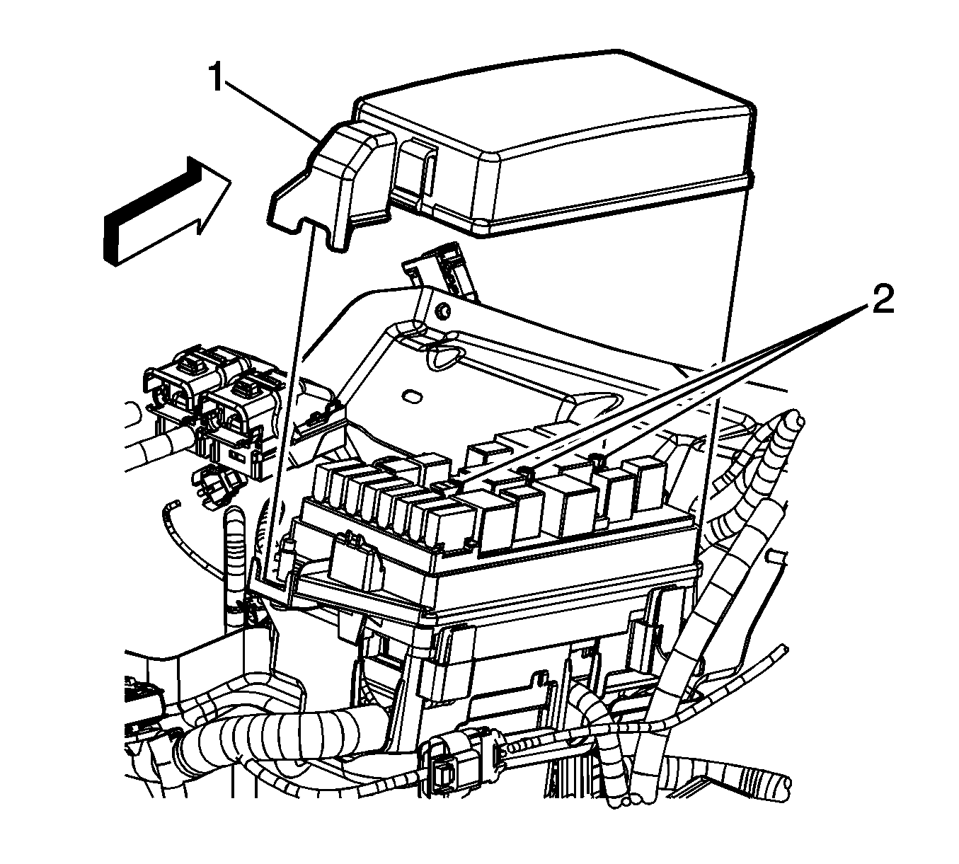
- Remove the underhood bussed electrical center (UBEC) cover (1).
- Remove the positive battery cable lead to UBEC nut and remove the 3 positive cables from the stud.
- Loosen the UBEC bolts (2), once loose, tap the bolts once in order the disengage the bolt from the electrical connectors.
- Disconnect the 3 electrical connectors from the rear of the UBEC. Note the color and location of each connector.
- Disengage the UBEC retaining tabs on the 4 corners and remove the UBEC.
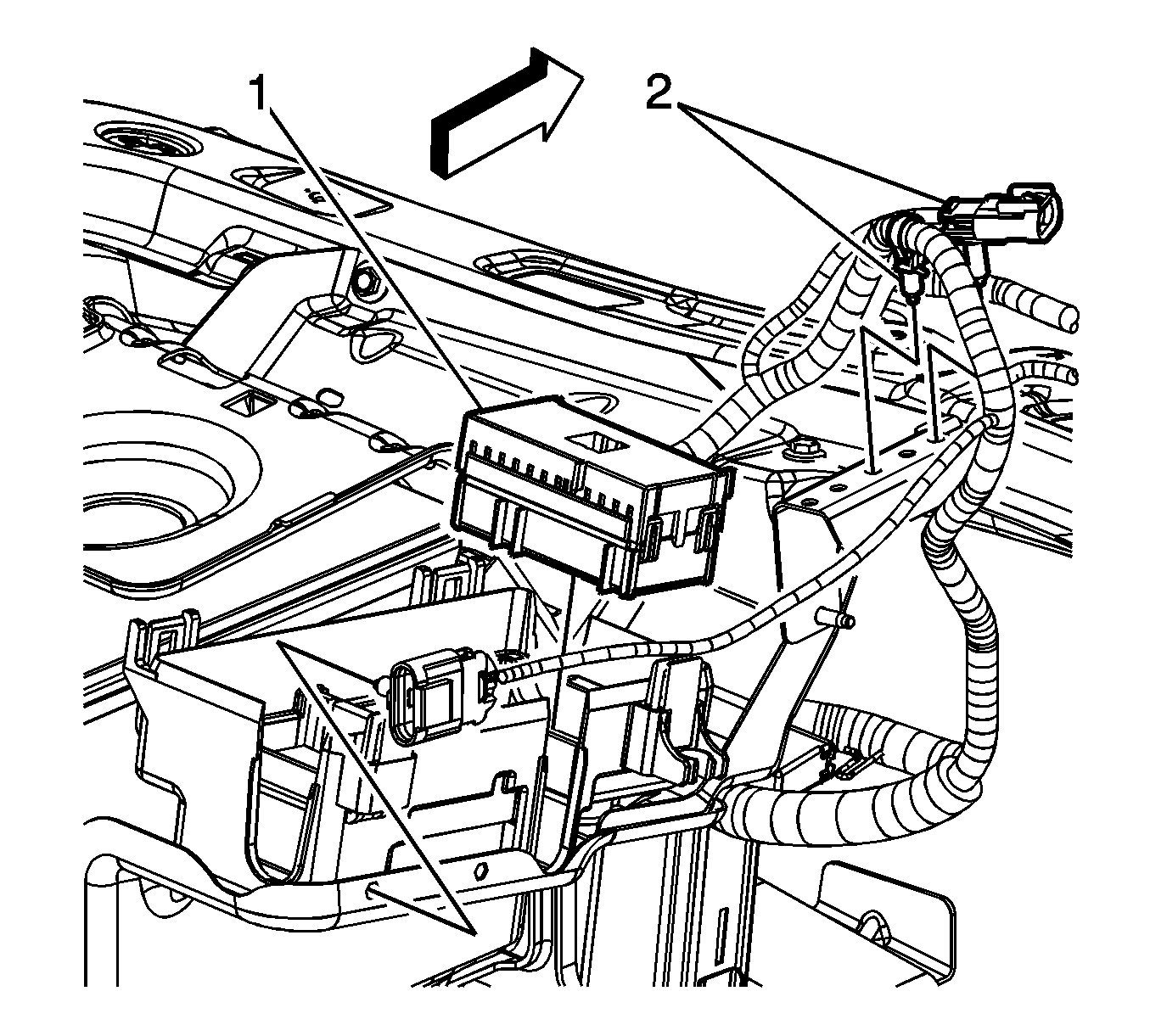
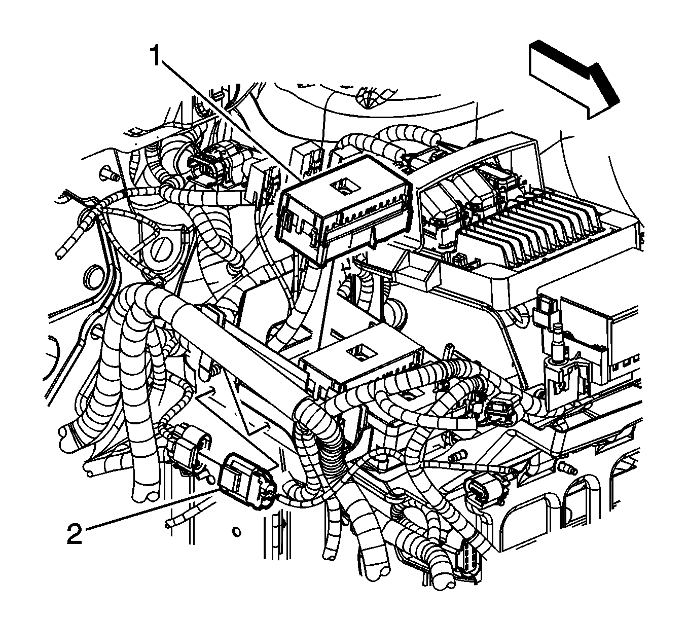
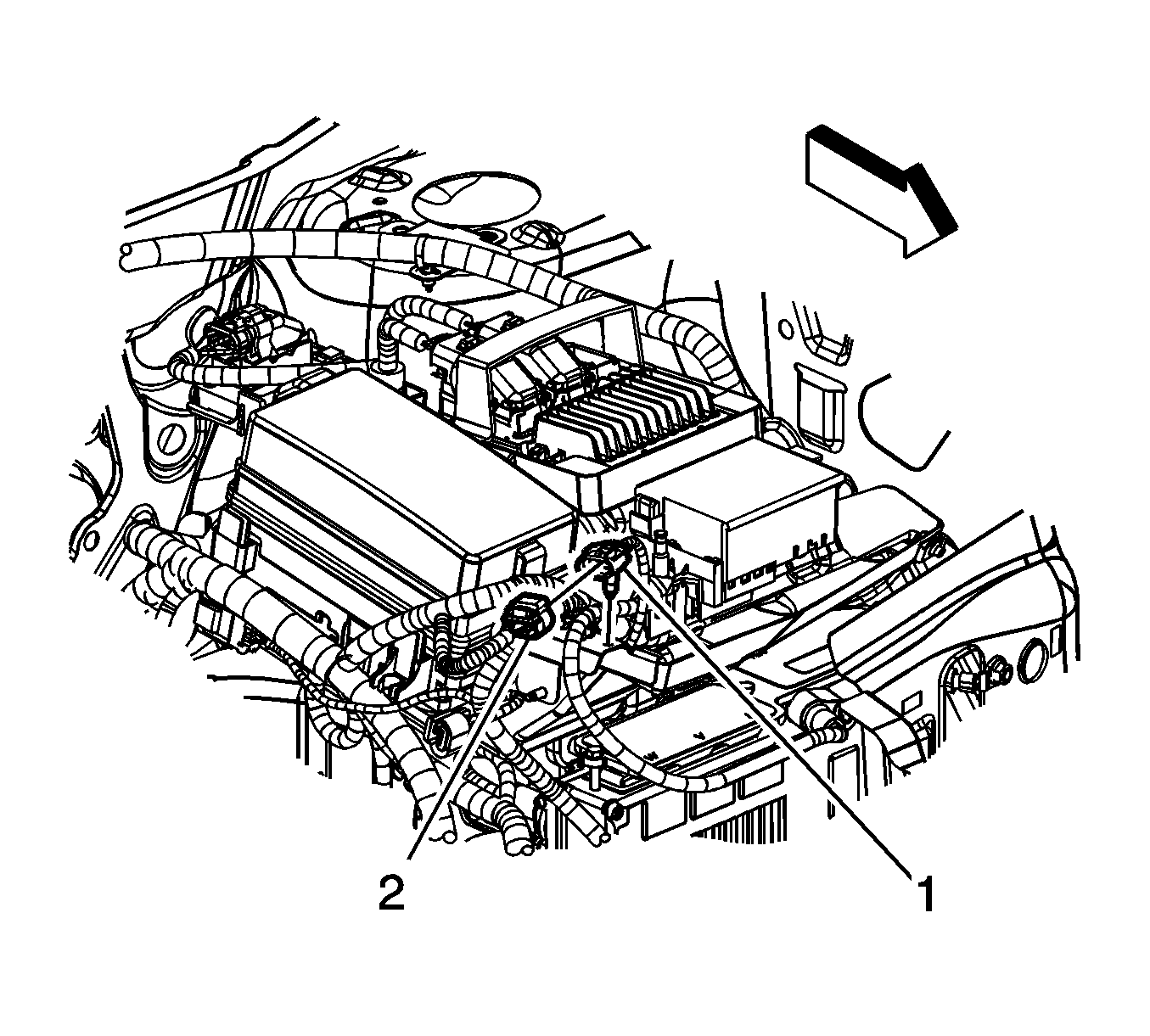
- Remove the forward lamp wiring harness clips (2) from the positive battery cable bracket.
- Remove the forward lamp wiring harness UBEC electrical connector (1) from the UBEC bracket and secure out of the way.
- Remove the engine wiring harness clip (2) from the battery tray.
- Remove the engine wiring harness UBEC electrical connector (1) from the UBEC bracket and secure out of the way.
- Remove the forward lamp wiring harness electrical connector (2) from the battery tray.
- Remove the body wiring harness UBEC electrical connector (1) from the UBEC bracket and secure out of the way.
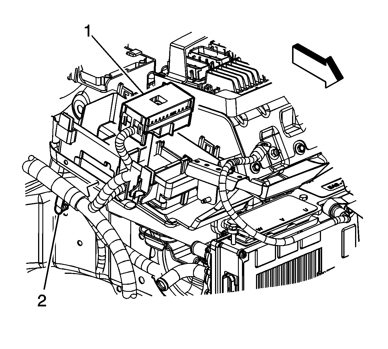
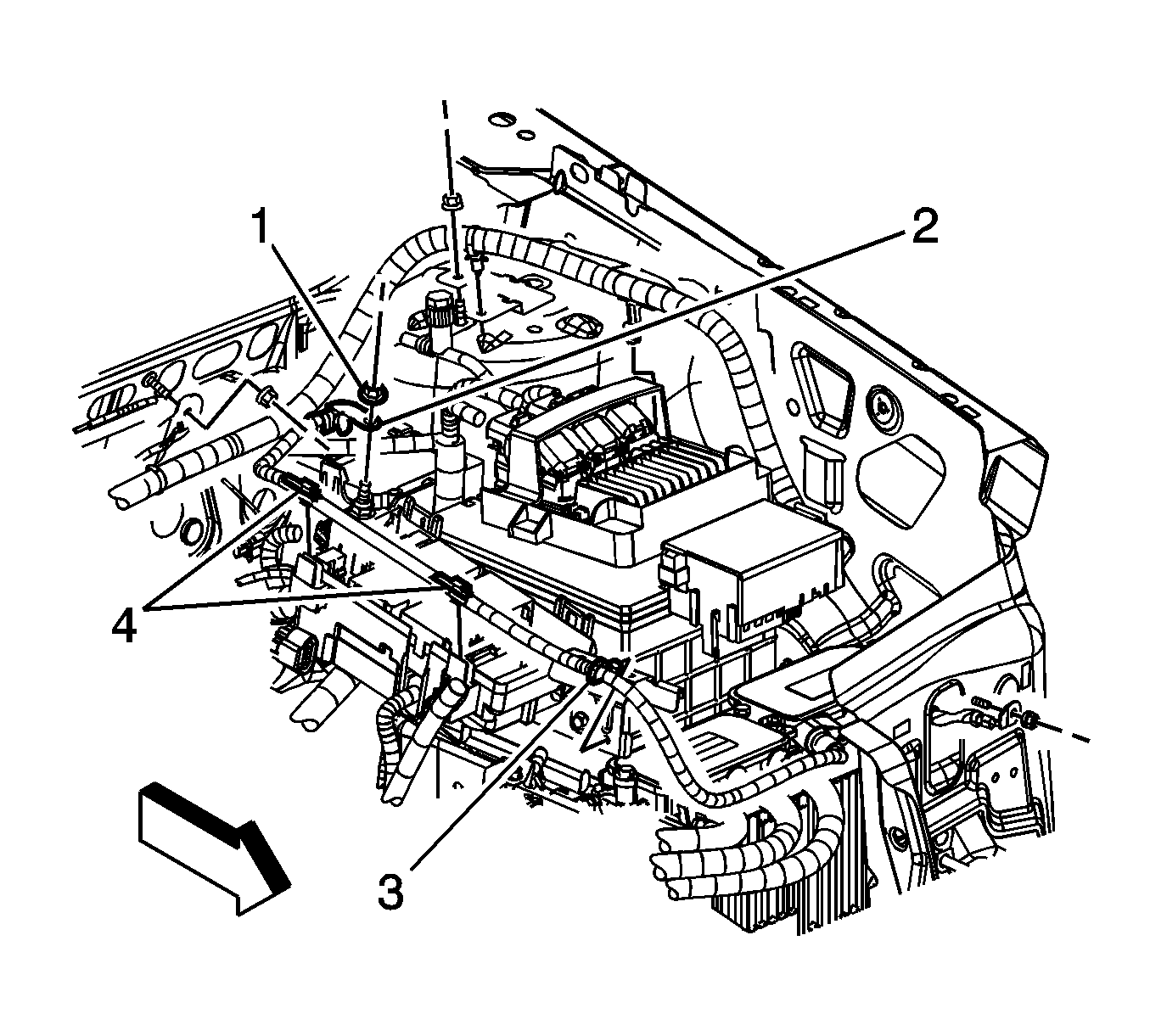
- Remove the 12 volt positive battery cable clips (4) from the UBEC bracket.
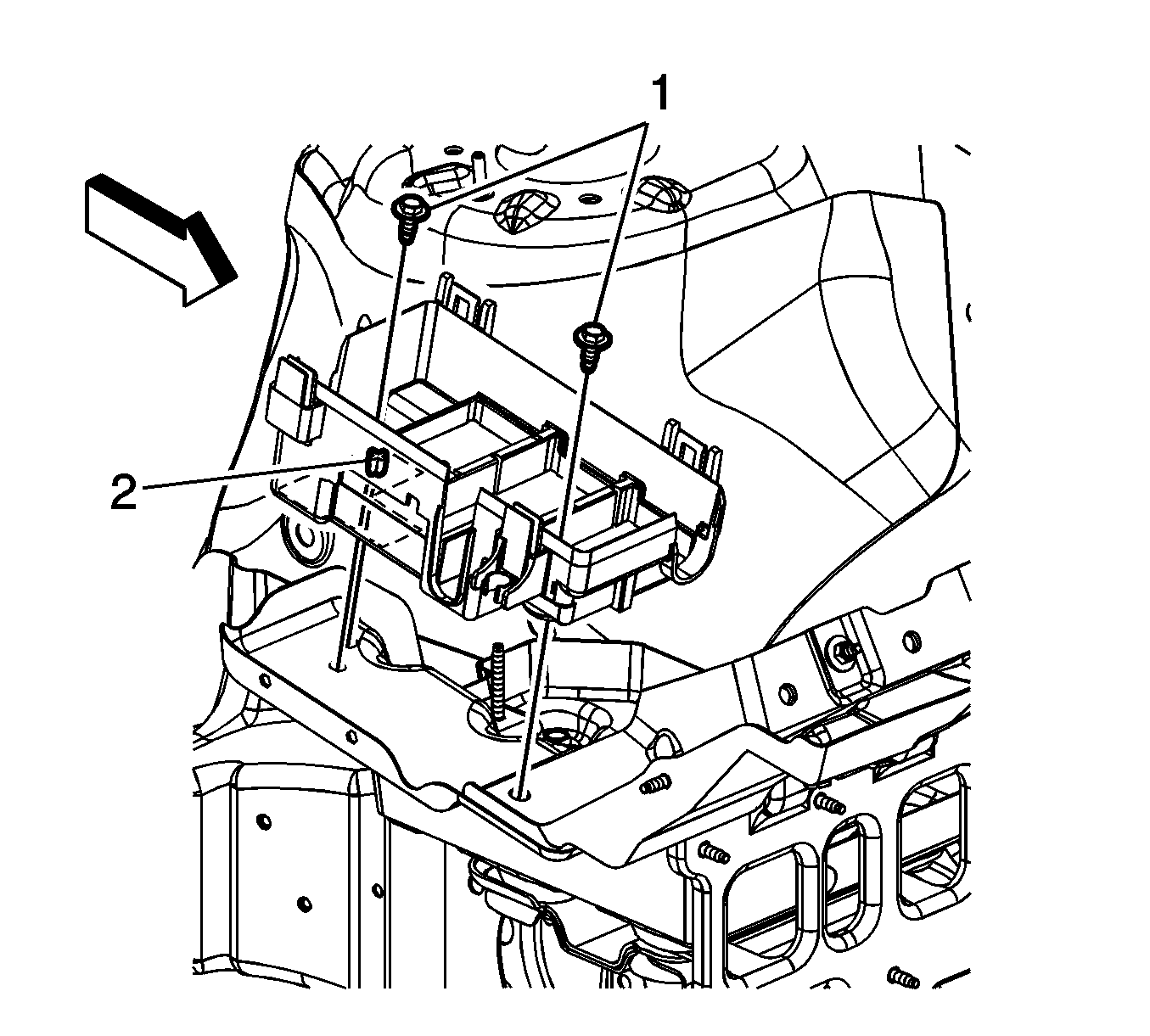
- Remove the UBEC bracket bolts (1) and bracket.
- Remove the forward lamp wiring harness electrical connector (1) from the positive battery cable bracket.
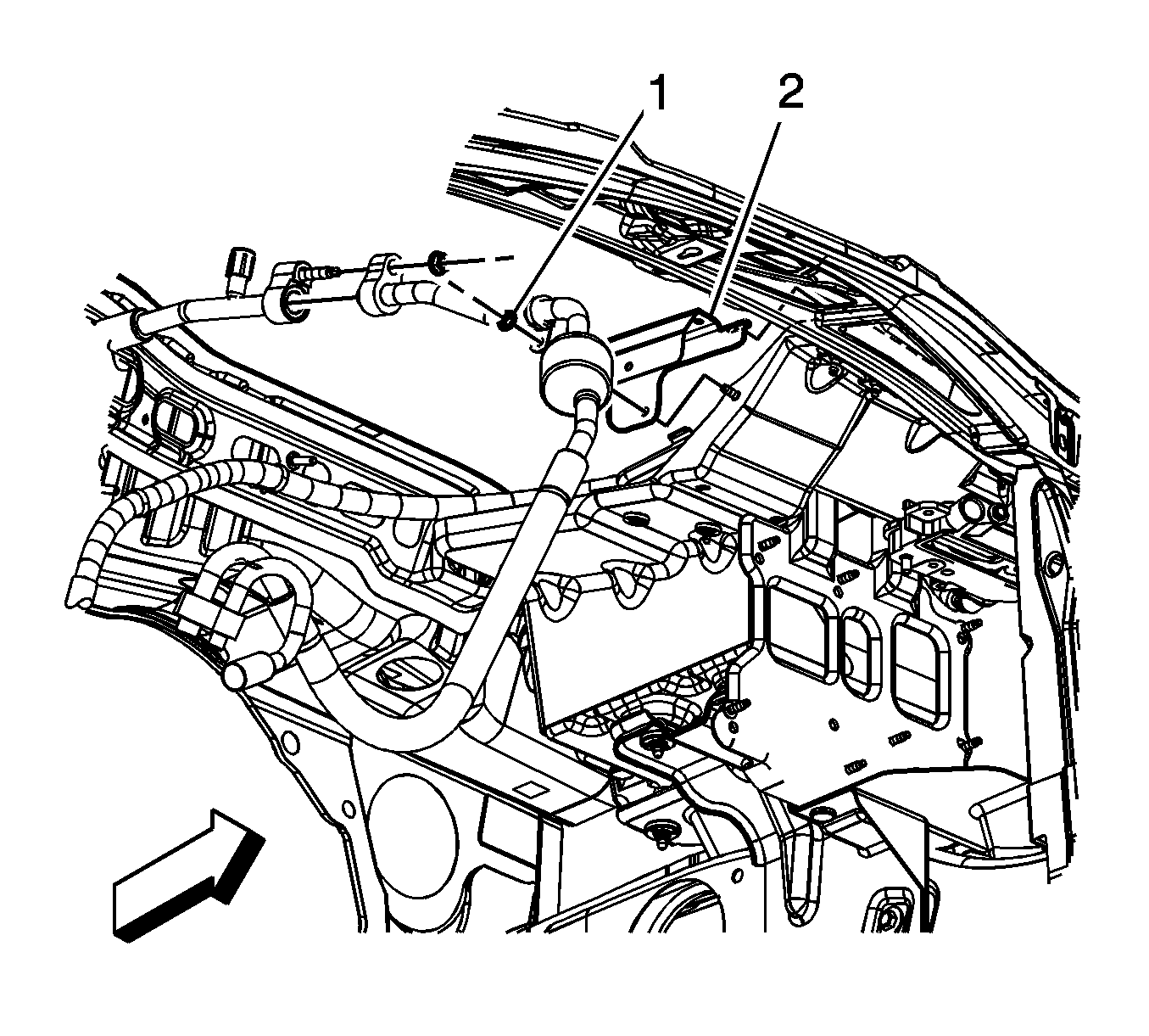
- Remove the air conditioning compressor and condenser hose nut (1) from generator control module bracket stud.
- Remove the positive battery cable bracket (2) from the stud.
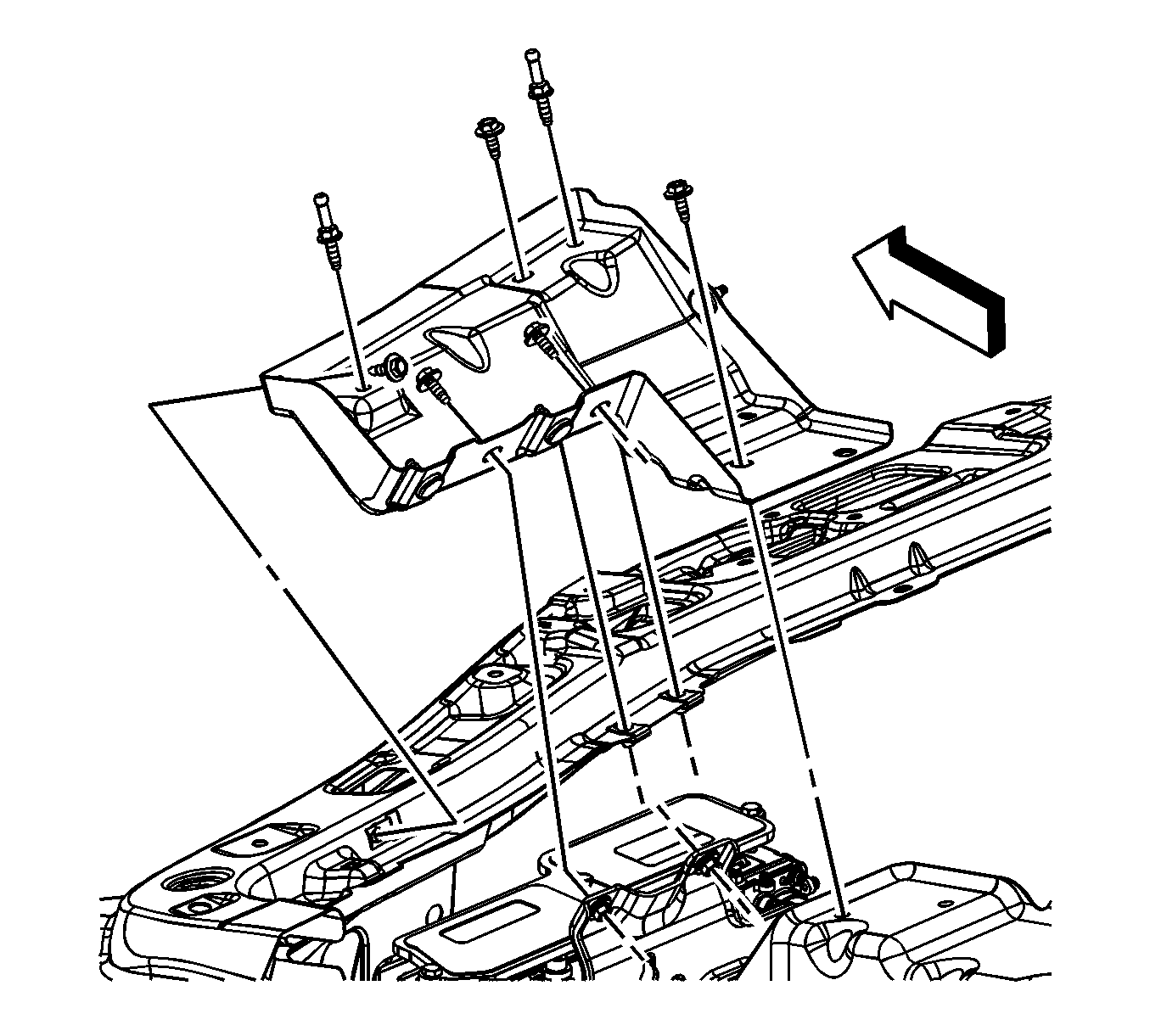
- Remove the generator control module bracket bolts and stud.
- Remove the generator control module bracket.
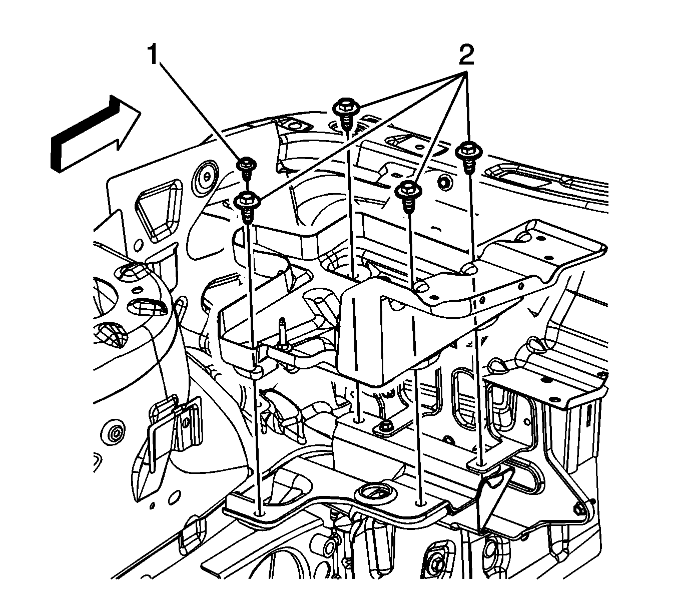
- Remove the battery tray bolts (1, 2) and battery tray.
Installation Procedure
- Install the battery tray and bolts.
- Install the generator control module bracket.
- Install the generator control module bracket bolts and stud.
- Install the positive battery cable bracket (2) to the stud.
- Install the air conditioning compressor and condenser hose nut (1) to generator control module bracket stud.
- Install the forward lamp wiring harness electrical connector (1) to the positive battery cable bracket.
- Install the UBEC bracket, align the locator pin (2) with the hole in the battery tray.
- Install the UBEC bracket bolts (1).
- Install the 12 volt positive battery cable clips (4) to the UBEC bracket.
- Position the body wiring harness UBEC electrical connector (1) to the UBEC bracket and snap into place.
- Install the forward lamp wiring harness electrical connector (2) to the battery tray.
- Position the engine wiring harness UBEC electrical connector (1) to the UBEC bracket and snap into place.
- Install the engine wiring harness clip (2) to the battery tray.
- Position the forward lamp wiring harness UBEC electrical connector (1) to the UBEC bracket and snap into place.
- Install the forward lamp wiring harness clips (2) to the positive battery cable bracket.
- Install the UBEC.
- Connect the 3 electrical connectors to the rear of the UBEC. Ensure that the color and location of each connector is correct.
- Tighten the UBEC bolts (2) until the bolt engages the electrical connector, an audible click will be heard.
- Install the 3 positive cables to the UBEC stud and install the positive battery cable lead nut.
- Install the UBEC cover (1).
- Install the battery. Refer to Battery Replacement .
Notice: Refer to Fastener Notice in the Preface section.

Tighten
| • | Tighten the bolt (1) to 10 N·m (89 lb in). |
| • | Tighten the bolts (2) to 22 N·m (16 lb ft). |

Tighten
Tighten the bolts/stud to 10 N·m (89 lb in).

Tighten
Tighten the nut to 20 N·m (15 lb ft).


Tighten
Tighten the bolts to 9 N·m (80 lb in).


Tighten
Tighten the bolts to 4 N·m (35 lb in).
Tighten
Tighten the nut to 15 N·m (11 lb ft).
