For 1990-2009 cars only
Removal Procedure
- Raise and support the vehicle. Refer to Lifting and Jacking the Vehicle .
- Remove the tire and wheel. Refer to Tire and Wheel Removal and Installation .
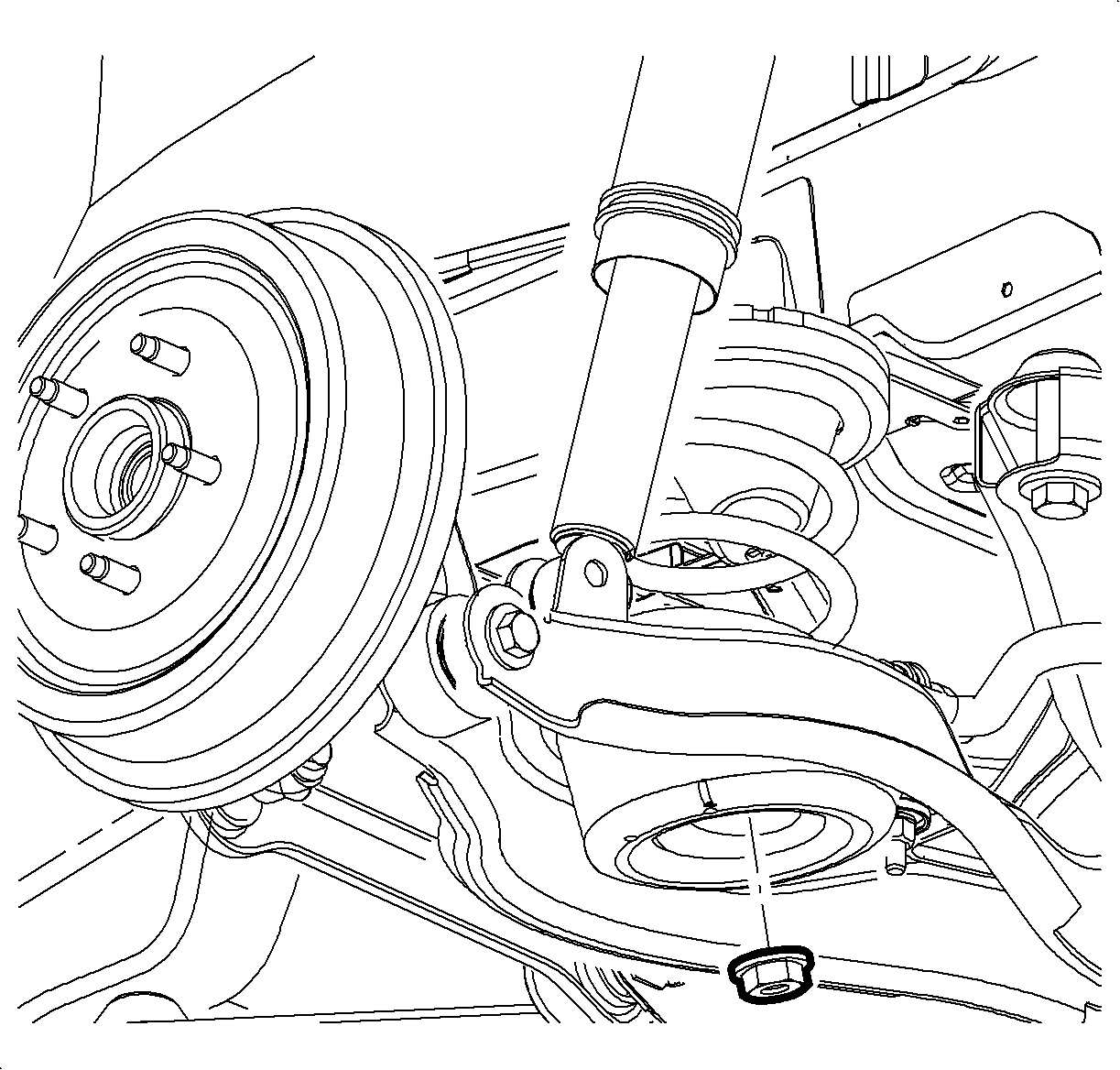
- Remove the stabilizer link to lower control arm nut.
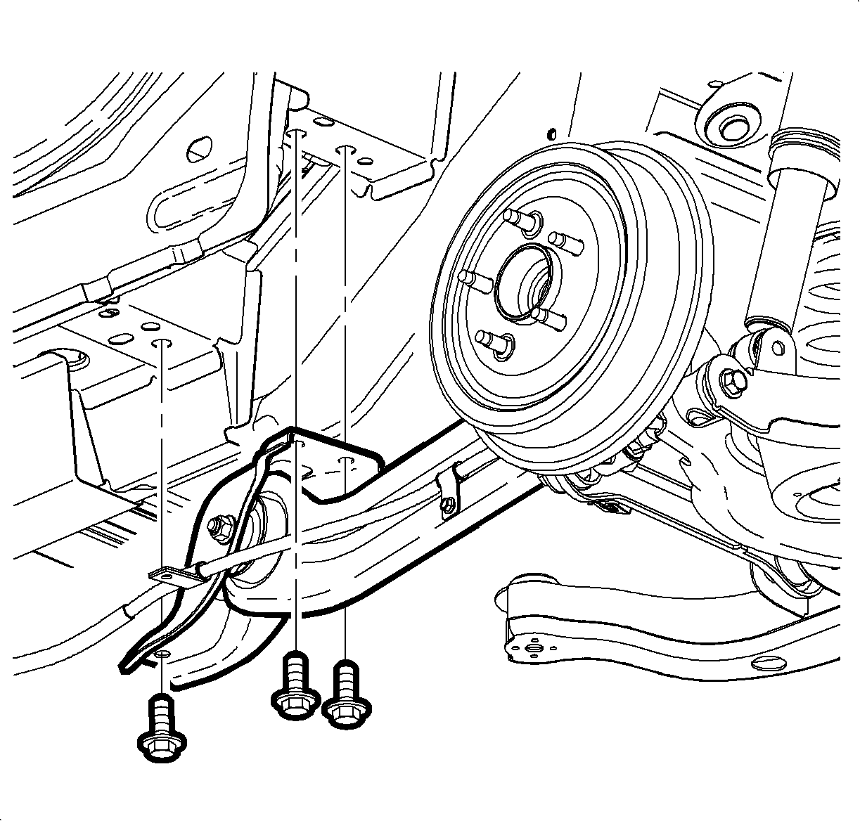
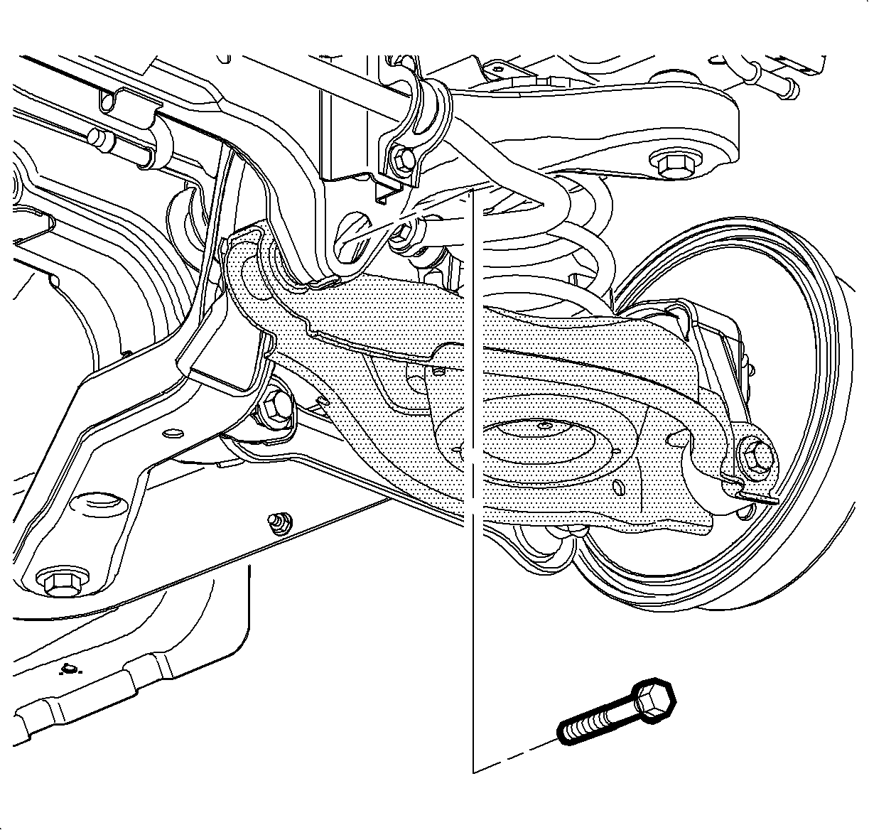
- Remove the trailing arm bracket to underbody bolts.
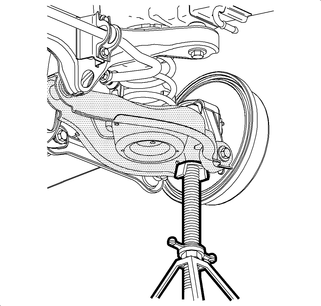
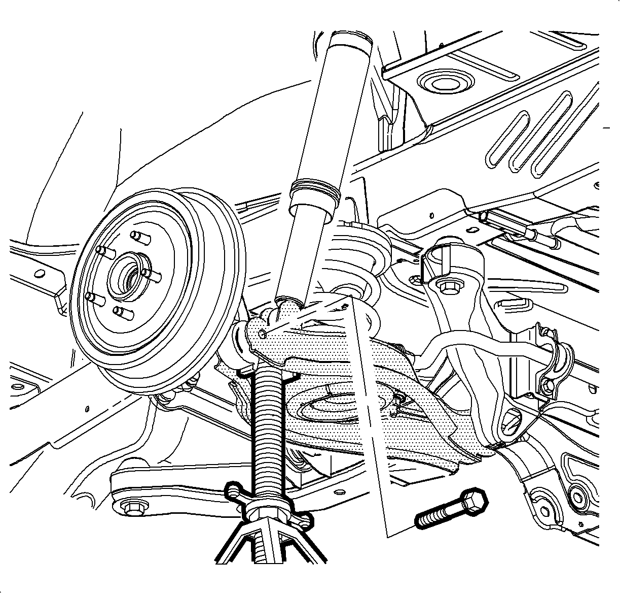
- Place a screw type jack stand under the lower control arm.
- Using the jackstand, compress the coil spring.
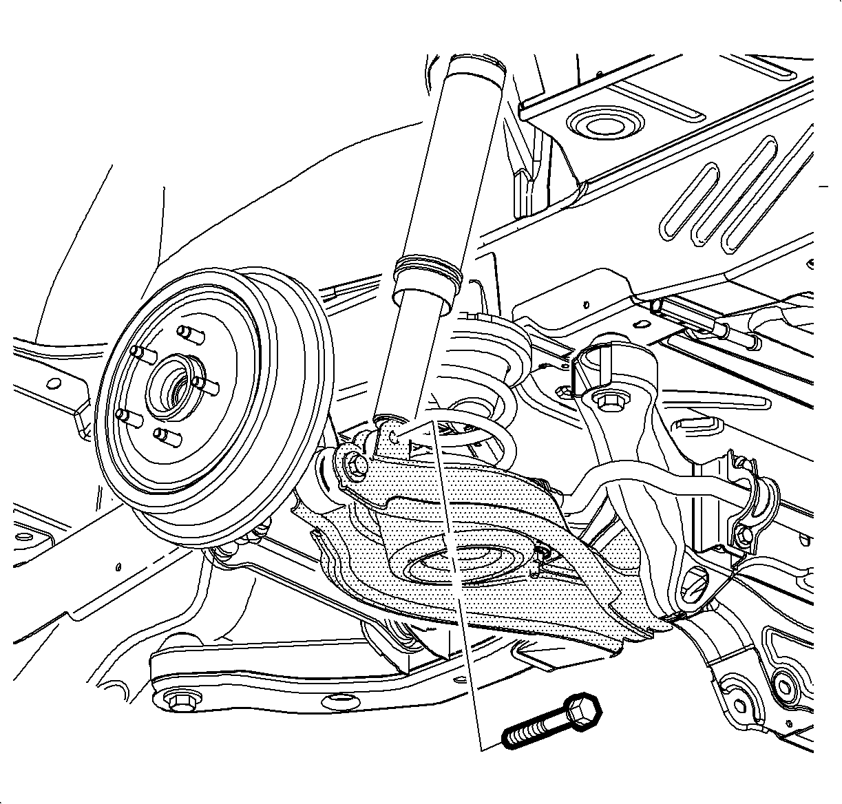
- Remove the lower shock bolt.
- Remove the jounce bumper nut at the lower control arm.
- Loosen the lower control arm to support the frame bolt.
- Remove the lower control arm to knuckle nut and bolt.
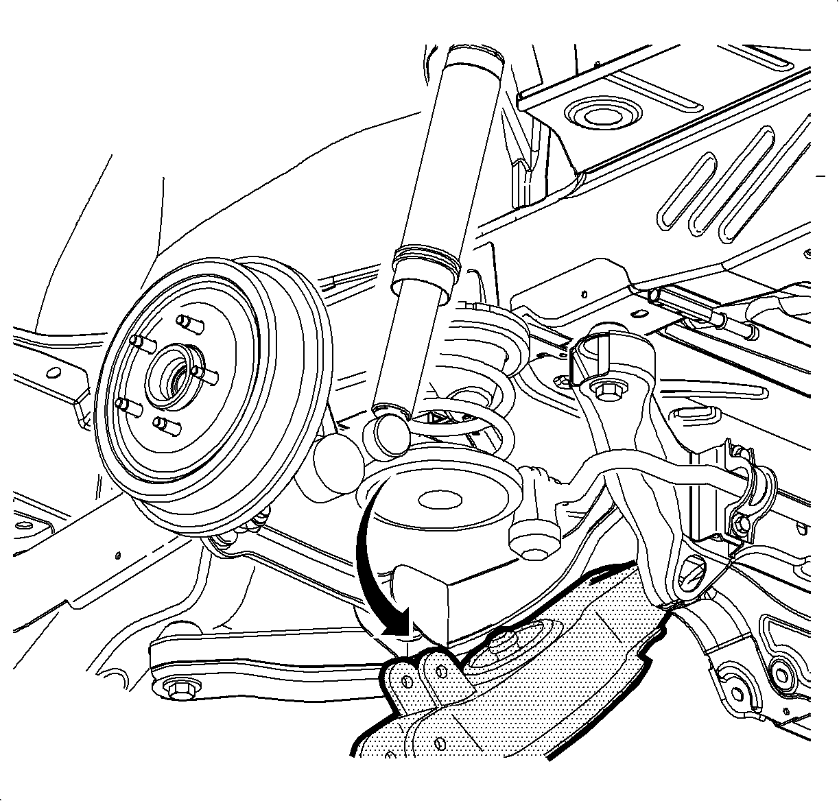
- Lower the control arm in order to unload the coil spring.
- Remove the coil spring.
- Remove the jounce bumper.
- Remove the control arm support nut and bolt.
- Remove the lower control arm.
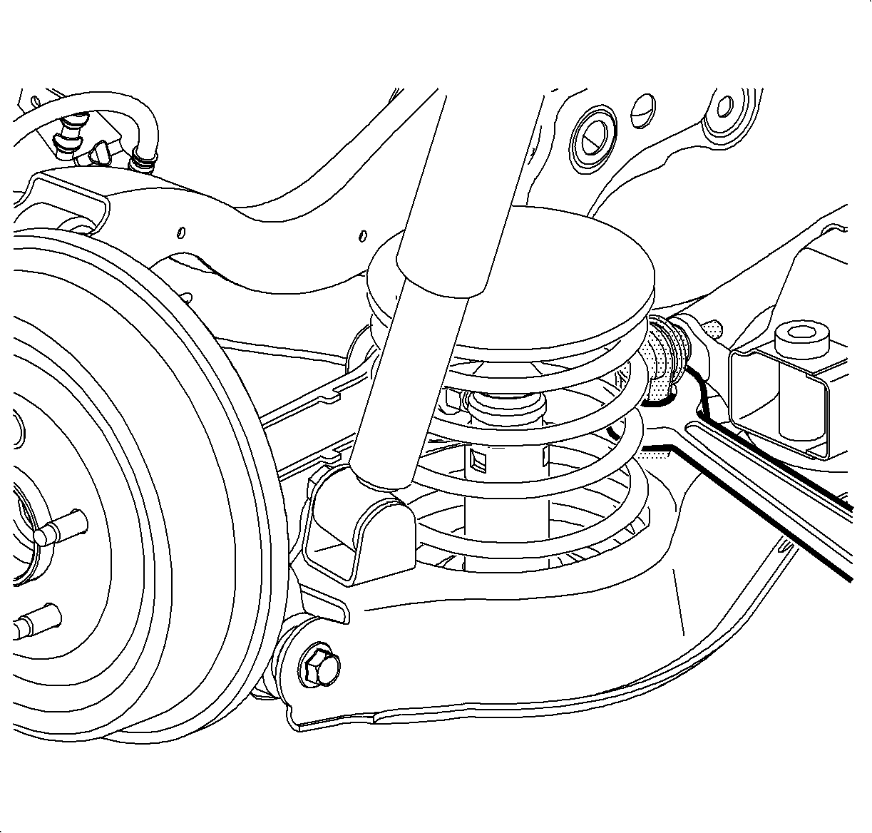
Important: Hold the link with a wrench during nut removal.
Installation Procedure
- Position the lower control to the support and hand tighten the bolt and nut.
- Install the spring and jounce bumper to the lower control arm; then hand tighten the jounce bumper nut.
- Position the spring with the rubber insulators into the vehicle.
- Use a screw type jack stand to compress the spring.
- Install the knuckle to the lower control arm.
- Tighten the lower control arm to support nut and bolt.
- Install the shock to the lower control arm.
- Remove the jack stand.
- Tighten the jounce bumper to the lower control arm nut.
- Install the stabilizer link to the lower control arm.
- Push the trailing arm upward to align the front bracket to the body bolt.
- Use a drift to aid in bracket alignment and install the remaining bolts.
- Install the tire and wheel. Refer to Tire and Wheel Removal and Installation .
- Lower the vehicle.
- Check the rear alignment. Refer to Wheel Alignment Measurement .


Important:
• Spray silicon lubricant on the insulators to aid in installation. • Ensure the spring is properly seated.
Notice: Refer to Fastener Notice in the Preface section.

Tighten
Tighten the lower control arm to knuckle bolt to 110 N·m (81 lb ft).
Tighten
Tighten the bolt to 110 N·m (81 lb ft).
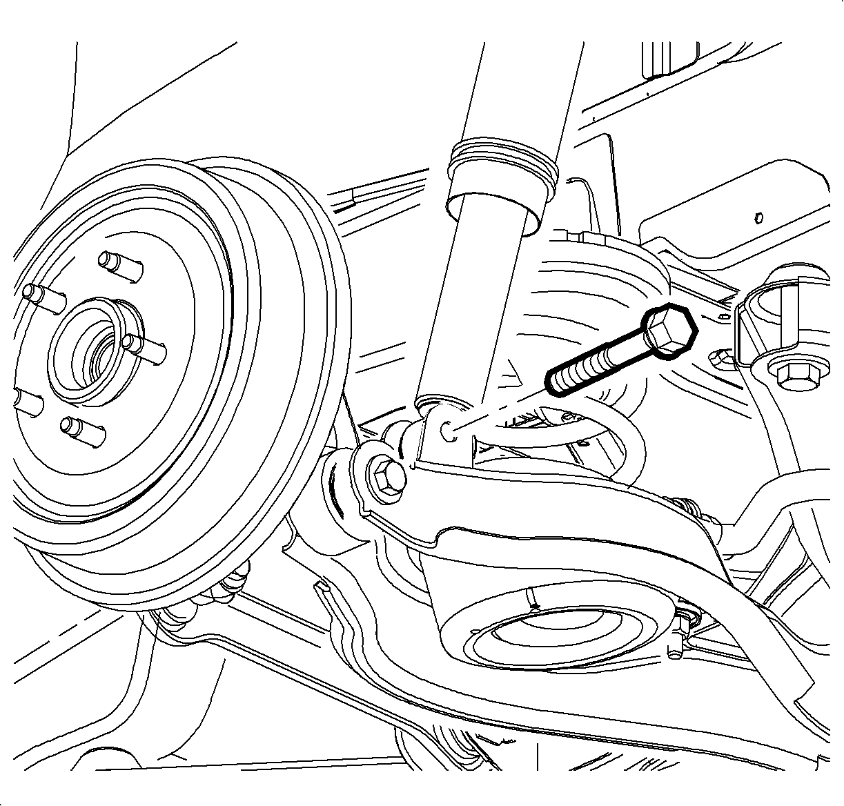
Tighten
Tighten the lower shock bolt to 105 N·m (77 lb ft).

Tighten
Tighten the nut to 63 N·m (46 lb ft).

Important: Hold the link with a wrench during nut installation.
Tighten
Tighten the nut to 15 N·m (11 lb ft).

Tighten
Tighten the bracket to body bolts to 110 N·m (81 lb ft).
