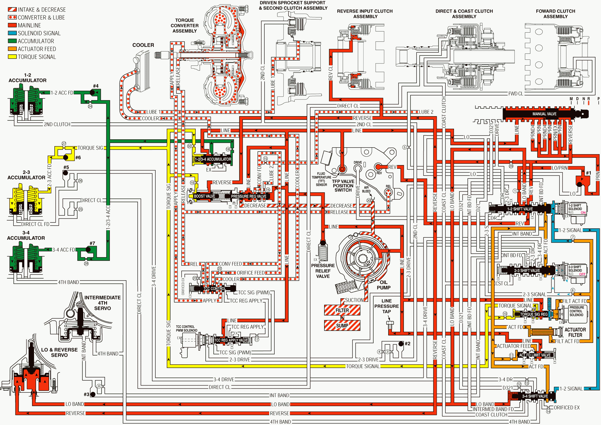
Reverse With Electronic Range Select Mode
Important: The explanation of each gear range is primarily limited to those changes from the previous range. However, some component descriptions are repeated for clarity and continuity. Also, refer to the appropriate General Motors Service manual for specific application information.
When you move the gear selector lever to the Reverse (R) position (from the Park position), the following changes occur in the transmission's hydraulic and electrical systems.
Pressure Regulation
Manual Valve
With the manual valve in the reverse position, line pressure is directed into the reverse fluid circuit, in addition to the PRND4 and the PRN fluid circuits, which were used in Park position.
Pressure Regulator and Boost Valves
Reverse fluid is routed to the boost valve. Reverse fluid assists torque signal fluid pressure. The addition of reverse fluid pressure increases the operating range of the line pressure in Reverse position.
A/T Fluid Pressure Manual Valve Position Switch (TFP Val. Position Sw.) Assembly
Reverse fluid is routed through the 1-2 shift valve and to the TFP Val. Position Sw. Assembly, which signals the PCM that the transmission is in Reverse position.
Reverse Clutch Applies
Reverse Clutch
Reverse clutch fluid pressure applies the reverse clutch.
Low and Reverse Band Remains Applied
1-2 Shift Solenoid Valve
The PCM keeps the solenoid valve energized in Reverse position. The 1-2 signal fluid pressure acts on the 1-2 shift valve.
1-2 Shift Valve
The 1-2 signal fluid pressure keeps the 1-2 shift valve in the downshifted position. Low/PRN fluid continues to feed the low band fluid circuit.
Low and Reverse Servo
Reverse fluid is routed to the outer area of the servo in order to increase the servo apply pressure in the Reverse position. The low band fluid is routed to the 3-4 shift valve. The pressure moves the 3-4 shift valve against the 1-2 signal fluid.
Torque Converter Clutch
Pressure Regulator (PR) Valve
Line pressure is routed through the PR valve and into the converter feed fluid circuit. Converter feed fluid is routed to the TCC feed limit valve.
TCC Feed Limit Valve
Converter feed fluid is routed through the valve and into the TCC feed limit fluid circuit.
TCC Regulated Apply Valve
A spring force holds the valve in the release position, thereby blocking line pressure.
TCC Control Valve
A spring force holds the valve in the release position. TCC feed limit fluid is routed into the release fluid circuit. Fluid returns from the converter in the apply fluid circuit. This fluid is routed through the valve and into the cooler fluid circuit.
Torque Converter
Release fluid pressure is routed to the torque converter in order to keep the TCC released. Fluid leaves the converter in the apply fluid circuit.
Cooler and Lube
Lube 1
Cooler fluid is routed through the transmission oil cooler, which is located in the vehicle radiator, and into the lube 1 fluid circuit. Lube 1 fluid is routed through the input shaft in order to lubricate the transmission components in the front of the transmission.
Lube 2
The lube 2 fluid circuit is fed by line pressure at the pressure regulator valve. Lube 2 fluid is routed through the oil feed pipes and into the forward clutch support. Lube 2 fluid provides lubrication in the rear of the transmission. The lube 2 fluid circuit is fed by line pressure at the pressure regulator valve. Lube 2 fluid is routed through the oil feed pipes and into the forward clutch support. Lube 2 fluid provides lubrication in the rear of the transmission.
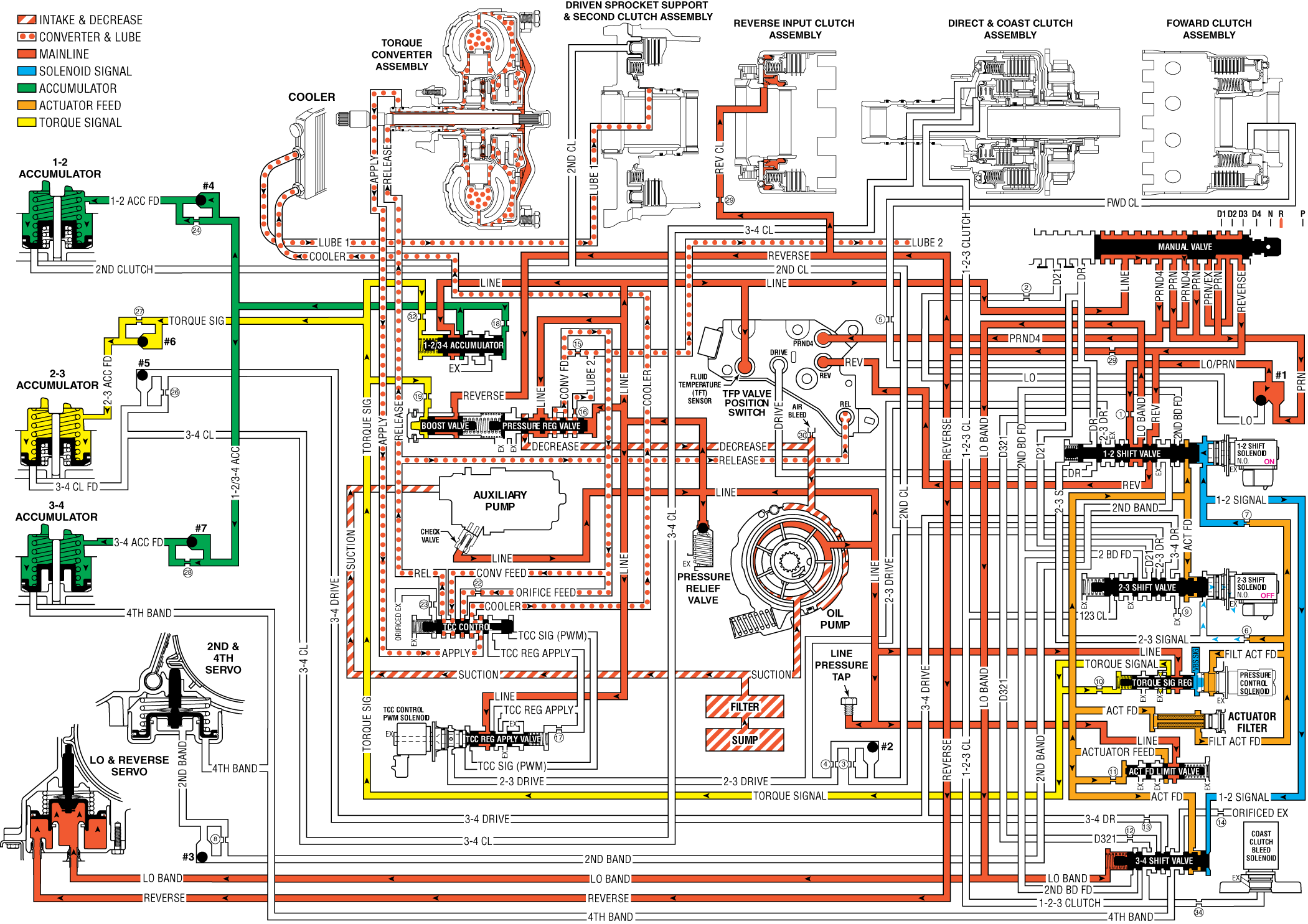
Reverse - With Electronic Range Select Mode

Reverse L4 Hybrid
Important: The explanation of each gear range is primarily limited to those changes from the previous range. However, some component descriptions are repeated for clarity and continuity. Also, refer to the appropriate General Motors Service manual for specific application information.
When you move the gear selector lever to the Reverse (R) position (from the Park position), the following changes occur in the transmission's hydraulic and electrical systems.
Under certain conditions the hybrid vehicles engine will shut off and the electric auxiliary transmission fluid pump will start running to keep the transmission pressurized and ready for the engine restart. This engine off condition is a fuel economy feature and the L4 hybrid transmission's electric auxiliary fluid pump is an enabling component.
Pressure Regulation
Manual Valve
With the manual valve in the reverse position, line pressure is directed into the reverse fluid circuit, in addition to the PRND4 and the PRN fluid circuits, which were used in Park position.
Pressure Regulator and Boost Valves
Reverse fluid is routed to the boost valve. Reverse fluid assists torque signal fluid pressure. The addition of reverse fluid pressure increases the operating range of the line pressure in Reverse position.
A/T Fluid Pressure Manual Valve Position Switch (TFP Val. Position Sw.) Assembly
Reverse fluid is routed through the 1-2 shift valve and to the TFP Val. Position Sw. Assembly, which signals the PCM that the transmission is in Reverse position.
Reverse Clutch Applies
Reverse Clutch
Reverse clutch fluid pressure applies the reverse clutch.
Low and Reverse Band Remains Applied
1-2 Shift Solenoid Valve
The PCM keeps the solenoid valve energized in Reverse position. The 1-2 signal fluid pressure acts on the 1-2 shift valve.
1-2 Shift Valve
The 1-2 signal fluid pressure keeps the 1-2 shift valve in the downshifted position. Low/PRN fluid continues to feed the low band fluid circuit.
Low and Reverse Servo
Reverse fluid is routed to the outer area of the servo in order to increase the servo apply pressure in the Reverse position. The low band fluid is routed to the 3-4 shift valve. The pressure moves the 3-4 shift valve against the 1-2 signal fluid.
Torque Converter Clutch
Pressure Regulator (PR) Valve
Line pressure is routed through the PR valve and into the converter feed fluid circuit. Converter feed fluid is routed to the TCC feed limit valve.
TCC Feed Limit Valve
Converter feed fluid is routed through the valve and into the TCC feed limit fluid circuit.
TCC Regulated Apply Valve
A spring force holds the valve in the release position, thereby blocking line pressure.
TCC Control Valve
A spring force holds the valve in the release position. TCC feed limit fluid is routed into the release fluid circuit. Fluid returns from the converter in the apply fluid circuit. This fluid is routed through the valve and into the cooler fluid circuit.
Torque Converter
Release fluid pressure is routed to the torque converter in order to keep the TCC released. Fluid leaves the converter in the apply fluid circuit.
Cooler and Lube
Lube 1
Cooler fluid is routed through the transmission oil cooler, which is located in the vehicle radiator, and into the lube 1 fluid circuit. Lube 1 fluid is routed through the input shaft in order to lubricate the transmission components in the front of the transmission.
Lube 2
The lube 2 fluid circuit is fed by line pressure at the pressure regulator valve. Lube 2 fluid is routed through the oil feed pipes and into the forward clutch support. Lube 2 fluid provides lubrication in the rear of the transmission. The lube 2 fluid circuit is fed by line pressure at the pressure regulator valve. Lube 2 fluid is routed through the oil feed pipes and into the forward clutch support. Lube 2 fluid provides lubrication in the rear of the transmission.
Reverse - L4 Hybrid

