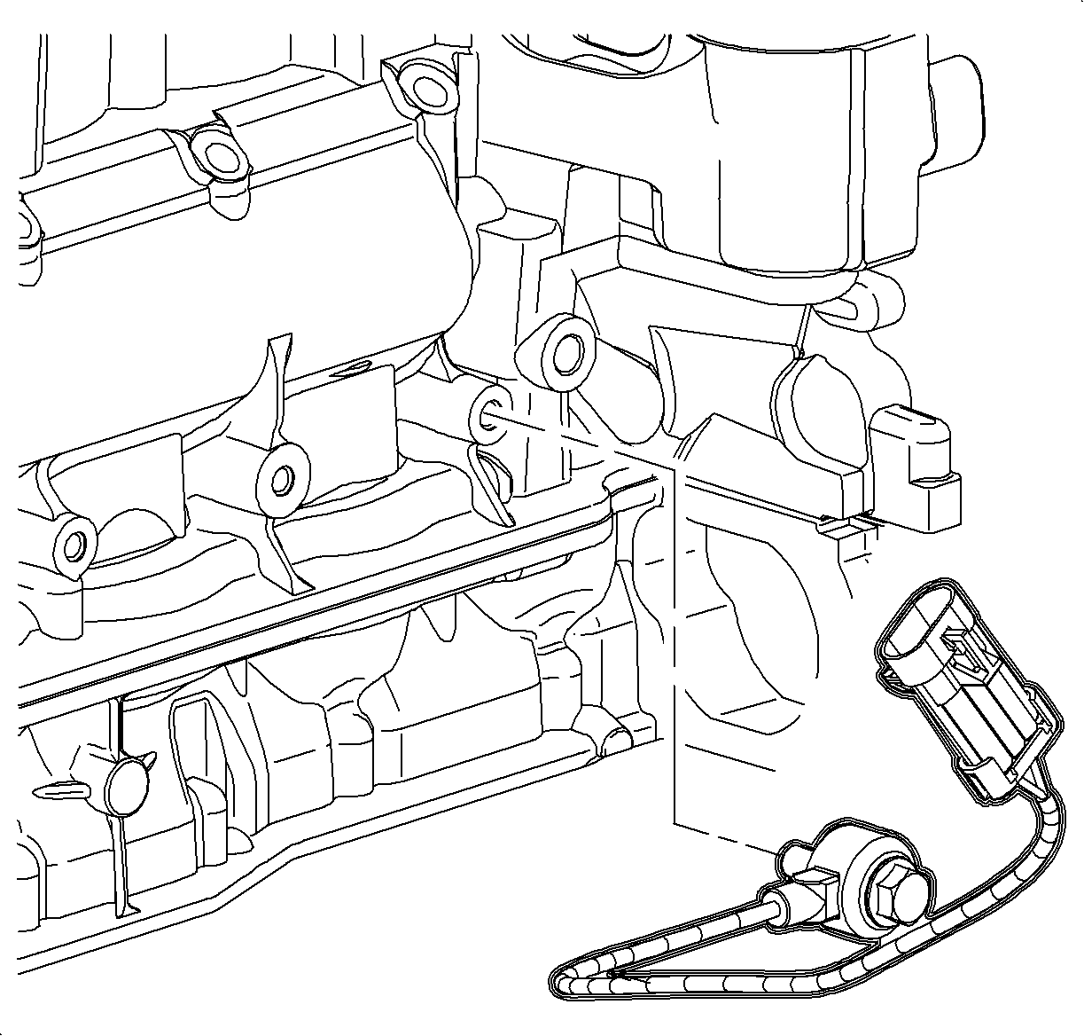
For 1990-2009 cars only
Removal Procedure
- Disconnect the negative battery cable. Refer to Battery Negative Cable Disconnection and Connection .
- Remove the knock sensor harness connector.
- Remove the knock sensor connector from the retaining clip by inserting a flat-bladed screwdriver between the connector and clip while sliding the connector upward.
- Remove the knock sensor.

Installation Procedure
- Insert the knock sensor pigtail connector with retaining clip into the intake manifold hole or slide the knock sensor pigtail connector over the retaining clip from the top.
- Connect the knock sensor harness connector. Push in the connector until a click is heard, then pull back to confirm a positive engagement.
- Install the knock sensor at the 9 o'clock position and attachment bolt.
- Connect the negative battery cable. Refer to Battery Negative Cable Disconnection and Connection .

Important: If a new knock sensor pigtail connector retaining clip is going to be used, the old one must be removed from the intake manifold. Use a push pin removal tool to remove the clip from the intake manifold.
Notice: Refer to Fastener Notice in the Preface section.
Important: The larger metal contact area of the knock sensor MUST be toward the engine block. A DTC P0327 may result if the sensor is installed backwards.
Tighten
Tighten the knock-sensor-engine block bolt to 25 N·m (18 lb ft).
