For 1990-2009 cars only
Removal Procedure
- Remove the left side insulator/closeout panel. Refer to Instrument Panel Insulator Panel Replacement - Left Side .
- Remove the communication interface module, if equipped. Refer to Communication Interface Module Replacement .
- Disconnect the electrical connector from the defroster actuator.
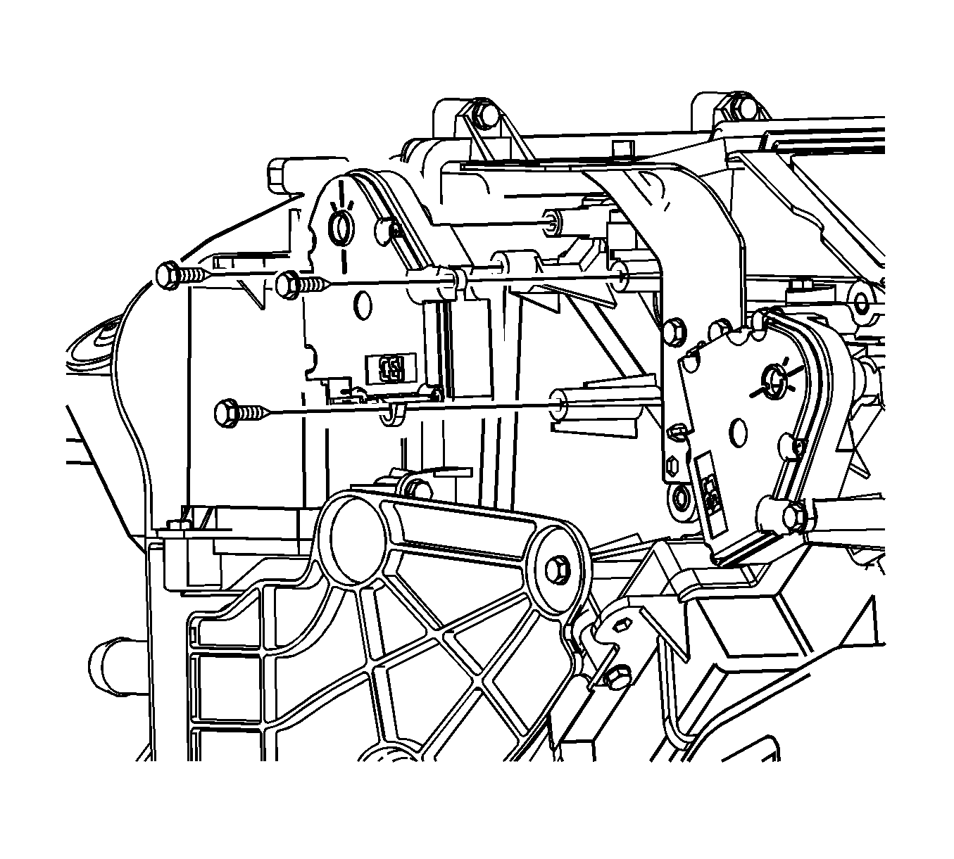
- Remove the defroster actuator screws from the HVAC module.
- Remove the defroster actuator from the HVAC module.

Installation Procedure
- Align the defroster actuator with the defroster door shaft and rotate into position.
- Install the defroster actuator screws to the HVAC module.
- Connect the electrical connector to the defroster actuator.
- Install the communication interface module, if equipped. Refer to Communication Interface Module Replacement .
- Install the left side insulator/closeout panel. Refer to Instrument Panel Insulator Panel Replacement - Left Side .
- Calibrate the mode actuators by simultaneously pushing the A/C and RECIRC buttons on the HVAC control module 3 times each, within 2 seconds of initial push.
- Cycle the ignition and verify proper operation.

Notice: Refer to Fastener Notice in the Preface section.
Tighten
Tighten the screws to 1 N·m (9 lb in).
Important: Any time a mode actuator or the HVAC control module is replaced, the HVAC control module must be calibrated to ensure proper air distribution.
| • | The A/C and RECIRC button LED's will flash while this calibration is taking place. |
| • | The calibration will take anywhere between 10-30 seconds depending on battery voltage. |
| • | The LED's will quit flashing when the calibration is complete. |
