Diagnostic Instructions
Circuit/System Description
The engine control module (ECM) supplies a high voltage signal to the fuel pump control module (FPCM) when the ECM detects that the ignition is ON. The high voltage signal from the ECM to the FPCM remains active for two seconds, unless the engine is in
Crank or Run. While this signal is being received, the FPCM closes the ground switch of the fuel pump and also supplies a varying voltage to the fuel tank pump module in order to maintain the desired fuel rail pressure.
The fuel system is a returnless on-demand design. The fuel pressure regulator is a part of the primary fuel tank module, eliminating the need for a return pipe from the engine. A returnless fuel system reduces the internal temperature of the fuel tank
by not returning hot fuel from the engine to the fuel tank. Reducing the internal temperature of the fuel tank results in lower evaporative emissions.
An electric turbine style fuel pump attaches to the primary fuel tank module inside the fuel tank. The fuel pump supplies high pressure fuel through the fuel filter, past the fuel pressure regulator, and through the fuel feed pipe to the fuel injection
system. The fuel pressure regulator has a T-joint that diverts the needed fuel to the fuel rail with the unused fuel dropping back into the reservoir of the primary fuel tank module. The primary fuel tank module contains a reverse flow check valve. The check
valve and the fuel pressure regulator maintain fuel pressure in the fuel feed pipe and the fuel rail in order to prevent long cranking times.
The primary fuel tank module also contains a primary jet pump and a secondary jet pump. Fuel pump flow loss, caused by vapor expulsion in the pump inlet chamber, is diverted to the primary jet pump and the secondary jet pump through a restrictive orifice
located on the pump cover. The primary jet pump fills the reservoir of the primary fuel tank module. The secondary jet pump creates a venturi action which causes the fuel to be drawn from the secondary side of the fuel tank, through the fuel transfer pipe, to
the primary side of the fuel tank.
Reference Information
Description and Operation
Fuel System Description
Electrical Information Reference
Scan Tool Reference
Control Module References for scan tool information
Special Tools Required
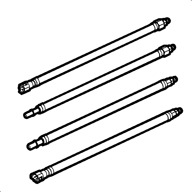
| • | J 43936 Fuel Pressure Adapter Cap |
| • | J 43937 Fuel Pressure Adapter Lines |
Circuit/System Verification
Important:
| • | Repair all fuel system related DTCs before performing this diagnostic. |
| • | Inspect the fuel system for damage or external leaks before proceeding. |
| • | Verify that adequate fuel is in the fuel tank before proceeding. |
| • | The fuel pump may need to be commanded ON a few times in order to obtain the highest possible fuel pressure. |
| • | Before proceeding with this test review the User Manual CH 48027-5 for Safety Information and Instructions. |
- Ignition OFF, all accessories OFF, install a
CH-48027-100 . Refer to
Fuel Pressure Gage Installation and Removal.
- Ignition ON, engine OFF, command the fuel pump ON with a scan tool. Verify the fuel pressure is between 384-425 kPa (56-62 psi) and does not decrease more than 100 kPa (14.5 psi) in 5 minutes.
Circuit/System Testing
Important:
| • | The fuel pump may need to be commanded ON a few times in order to obtain the highest possible fuel pressure. |
| • | DO NOT start the engine. |
- Ignition ON, engine OFF, command the fuel pump ON with a scan tool and observe the fuel pressure gage while the fuel pump is operating. Verify the fuel pressure is between 384-425 kPa (56-62 psi).
| ⇒ | If the fuel pressure is greater than the specified range, replace the primary fuel tank module. |
| ⇒ | If the fuel pressure is less than the specified range, test, inspect, and repair the items listed below. If all items
test normal, replace the primary fuel tank module. |
| • | Restricted fuel feed pipe |
| • | Inspect the harness connectors and the ground circuits of the fuel pump for poor connections. |
- Verify that the fuel pressure does not decrease more than 100 kPa (14.5 psi) in 5 minutes.
| ⇒ | If the fuel pressure decreases more than the specified value, perform the following procedure: |
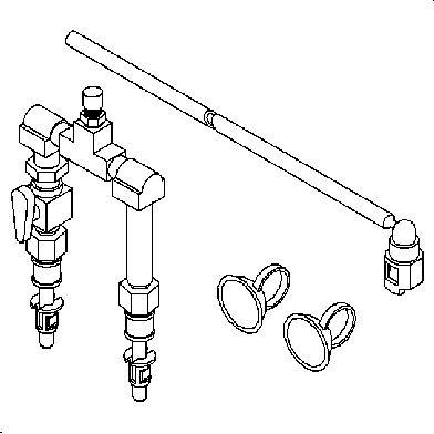
| 2.3. | Connect the chassis fuel feed hose to the inlet side of
SA9127E-7 using the
J 43937 . |
| 2.4. | Connect the engine compartment fuel pipe to the ON/OFF valve side of the
SA9127E-7 using the
J 43937 . |
| 2.7. | Ignition ON, command the fuel pump ON with a scan tool and bleed the air from the
CH-48027-100 . |
| 2.8. | Command the fuel pump ON for a minimum of 10 seconds with a scan tool. |
| 2.10. | Monitor the fuel pressure for 5 minutes. |
| ⇒ | If the fuel pressure decreases more than 55 kPa (8 psi) within the specified time, locate and replace the leaking fuel injectors. |
| ⇒ | If the fuel pressure does not decrease more than 55 kPa (8 psi)
within the specified time, replace the primary fuel tank module. |
- Relieve the fuel pressure to 69 kPa (10 psi). Verify that the fuel pressure does not decrease more than 14 kPa (2 psi) in 5 minutes.
| ⇒ | If the fuel pressure decreases more than the specified value, replace the primary fuel tank module. |
- Operate the vehicle within the conditions of the customer's concern while monitoring the fuel pressure with the
CH-48027-100 . The fuel pressure should not drop off during acceleration, cruise, or hard cornering.
| ⇒ | If the fuel pressure drops off, test, inspect, and repair the items listed below. If all items test normal, replace the primary fuel tank module. |
| • | Restricted fuel feed pipe |
| • | Inspect the harness connectors and the ground circuits of the fuel pump for poor connections. |
- If the fuel system tests normal, refer to
Symptoms - Engine Controls.
Repair Instructions
Perform the
Diagnostic Repair Verification after completing the diagnostic procedure.
