For 1990-2009 cars only
Special Tool
EL-48569 Terminal Covers
Removal Procedure
- Remove the drive motor generator control module. Refer to Drive Motor Generator Battery Control Module Replacement
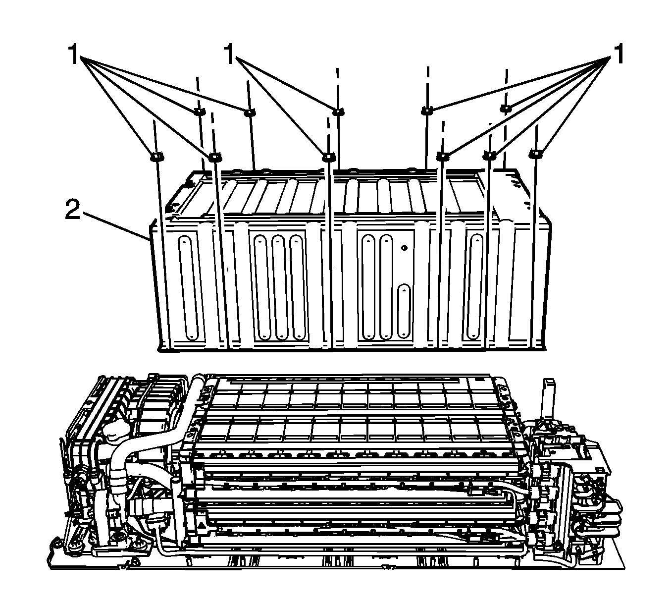
- Remove the battery center cover fasteners (1) and the center cover (2).
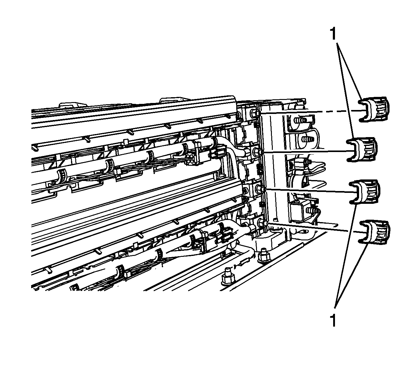
- Remove the plastic terminal covers (1).
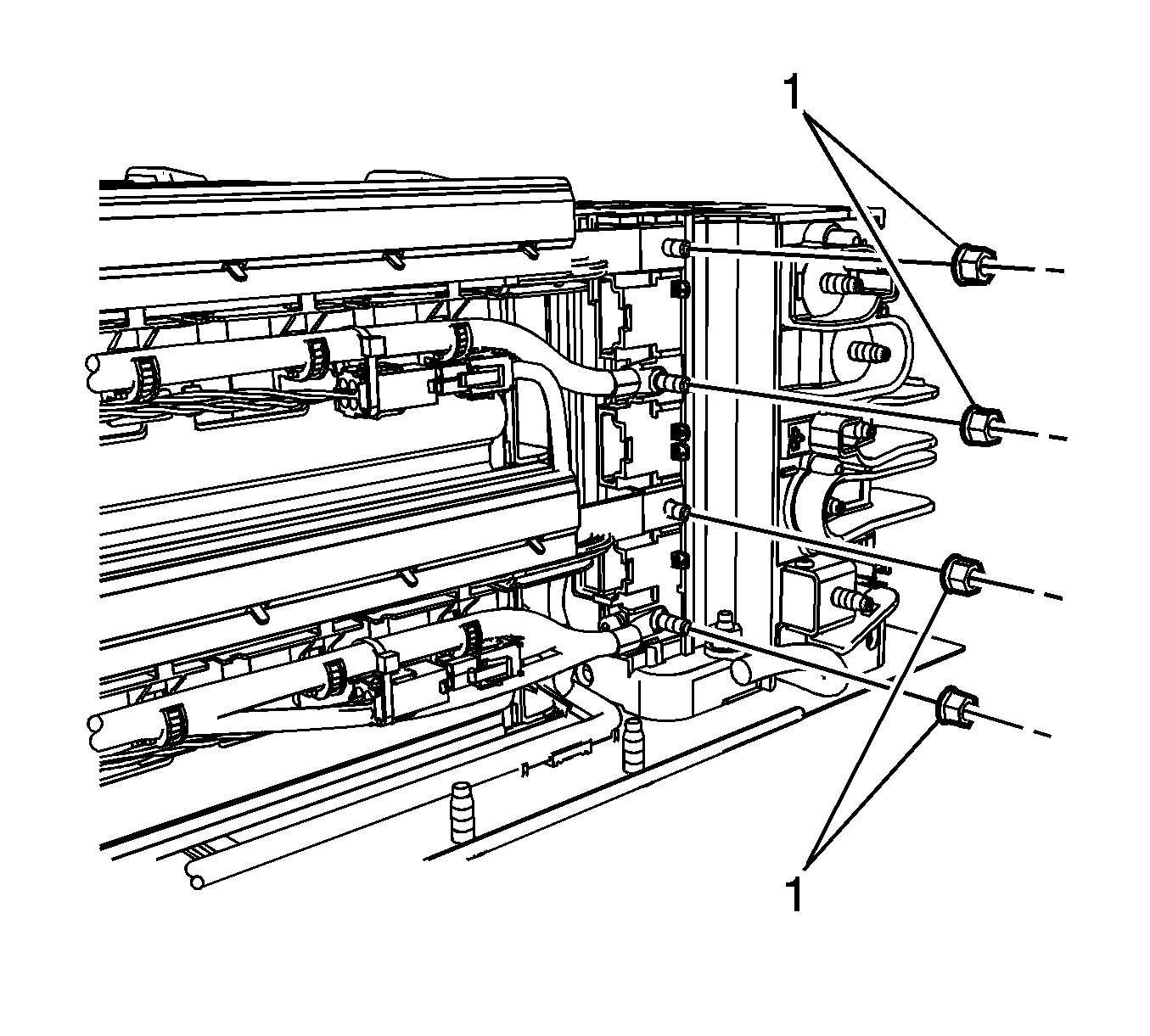
- Remove the terminal fasteners (1).
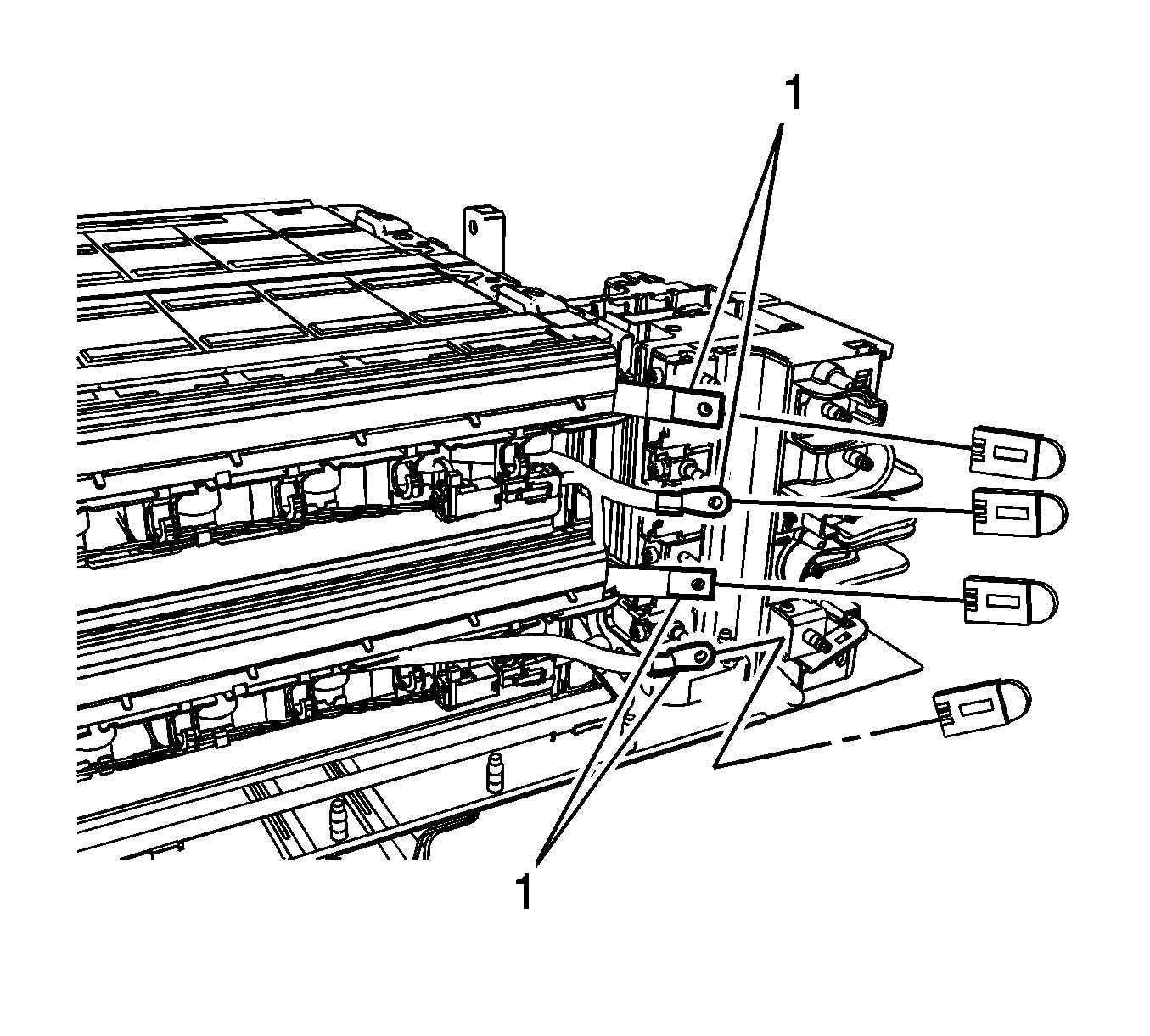
- Reposition the battery terminal cables (1) and using the EL-48569 covers , cover the terminals.
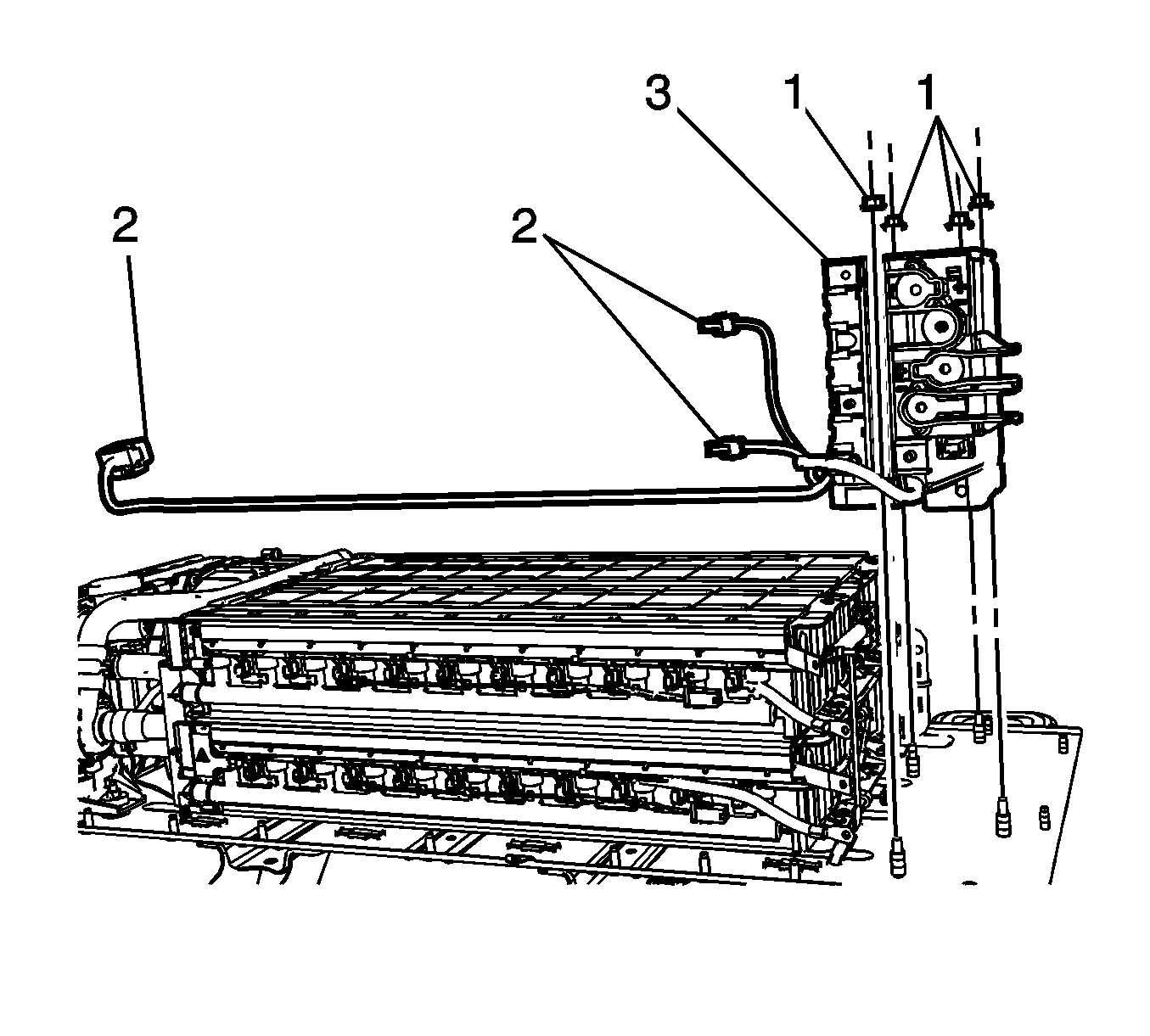
- Remove the module fasteners (1).
- Disconnect the electrical connectors (2).
- Remove the drive motor battery disconnect control module (3).
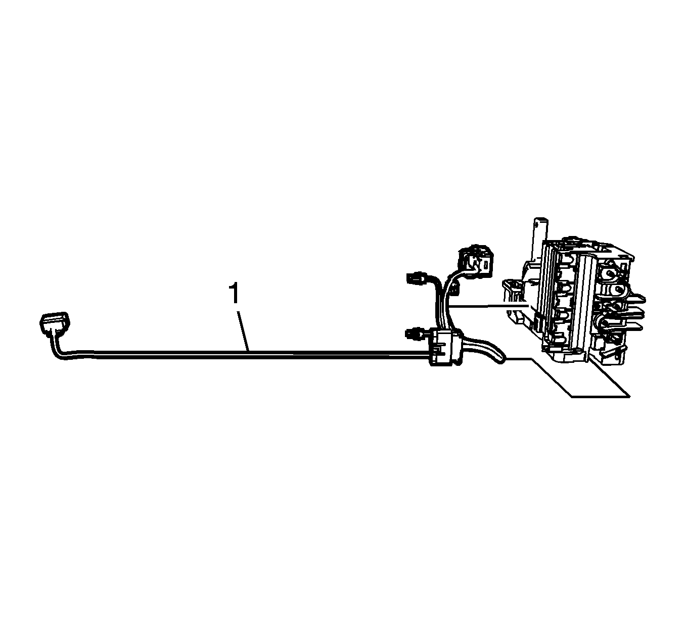
- Remove the drive motor battery sensor module wiring harness (1).
Danger: Always perform the High Voltage Disabling procedure prior to servicing any High Voltage component or connection. Personal Protection Equipment (PPE) and proper procedures must be followed.
The High Voltage Disabling procedure will perform the following tasks:| • | Identify how to disable high voltage. |
| • | Identify how to test for the presence of high voltage. |
| • | Identify condition under which high voltage is always present and personal protection equipment (PPE) and proper procedures must be followed. |
Warning: High Voltage (HV) cables are not repairable. After disconnecting HV cables, protect and insulate ring terminal ends immediately with the EL-48569 terminal covers and UL® Listed, or equivalent, insulation tape rated at a minimum of 600 volts. Damage caused to unprotected terminal ends will result in cable replacement.
Installation Procedure
- Install the drive motor battery sensor module wiring harness (1).
- Install the drive motor battery disconnect control module (3).
- Connect the electrical connectors (2).
- Install the module fasteners (1) and tighten to 9 N·m(80 lb in) .
- Remove the EL-48569 covers from the terminals (1).
- Reposition the cable terminals and install the terminal fasteners (1) and tighten to 9 N·m(80 lb in) .
- Remove the EL-48569 covers , from the 300 Volt positive and negative terminals.
- Install the plastic terminal covers (1).
- Install the battery center cover fasteners (1) and the center cover (2).
- Install the drive motor generator control module. Refer to Drive Motor Generator Battery Control Module Replacement
- Enable the High Voltage system. Refer to High Voltage Enabling


Caution: Refer to Fastener Caution in the Preface section.


