Removal Procedure
Caution: Do not allow smoking or the use of open flames in the area where work on the fuel or EVAP system is taking place. Anytime work is being done on the fuel system, disconnect the negative battery cable, except for those tests where battery voltage is required.
Caution: Refer to Gasoline/Gasoline Vapors Caution in the Preface section.
Caution: Whenever fuel lines are removed, catch fuel in an approved container. Container opening must be a minimum of 300 mm (12 in) diameter to adequately catch the fluid.
Notice: Fuel/Vapor lines cannot be spliced or repaired. The line must be replaced (if damaged) with the same type of line.
- Disconnect the negative battery cable. Refer to Battery Negative Cable Disconnection and Connection .
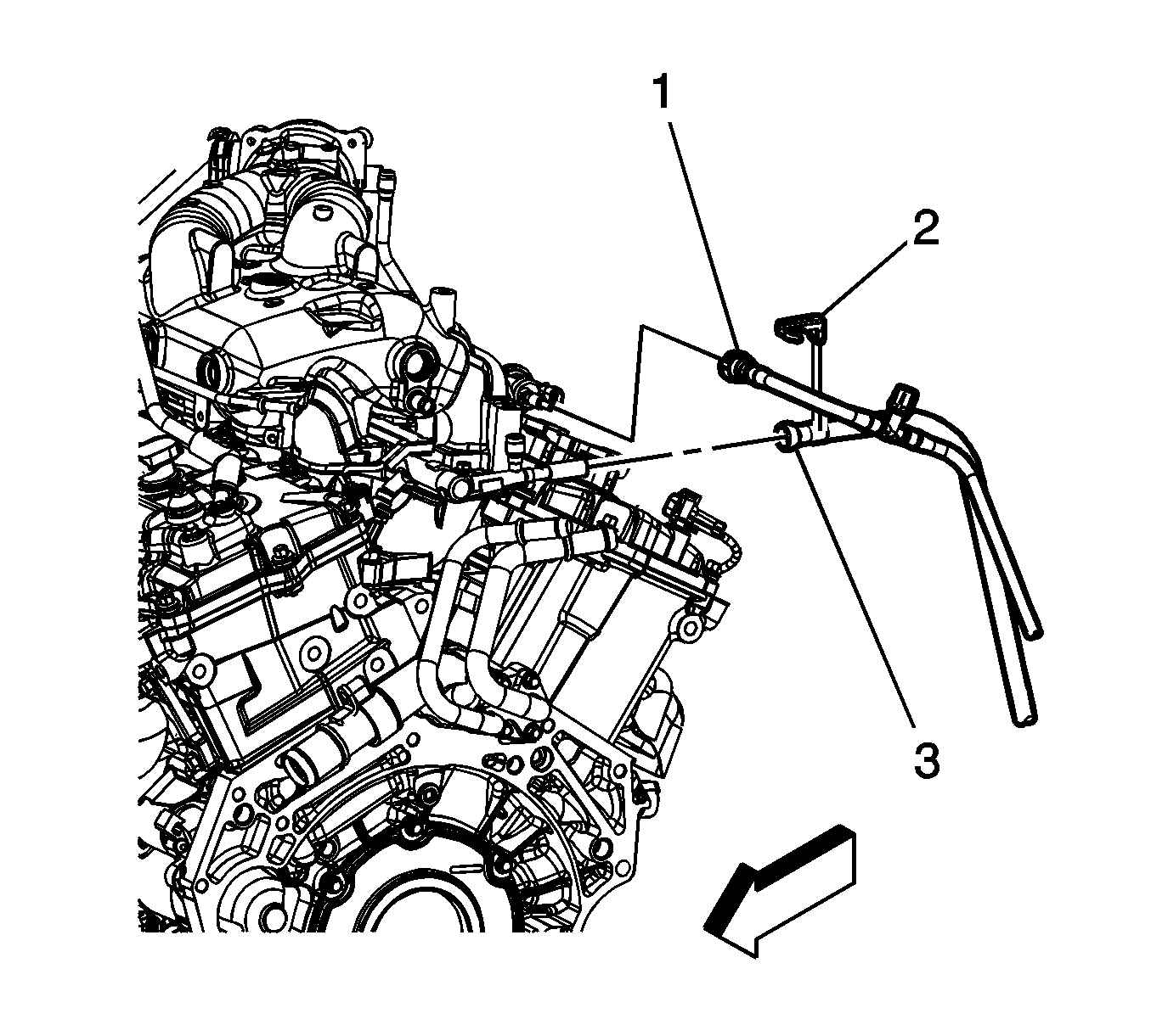
- Disconnect the fuel feed pipe quick connect fitting (3) from the fuel rail. Refer to Metal Collar Quick Connect Fitting Service .
- Disconnect the evaporative emission (EVAP) pipe quick connect fitting (3) from the EVAP purge solenoid. Refer to Plastic Collar Quick Connect Fitting Service .
- Cap the fuel and EVAP lines in order to prevent system contamination.
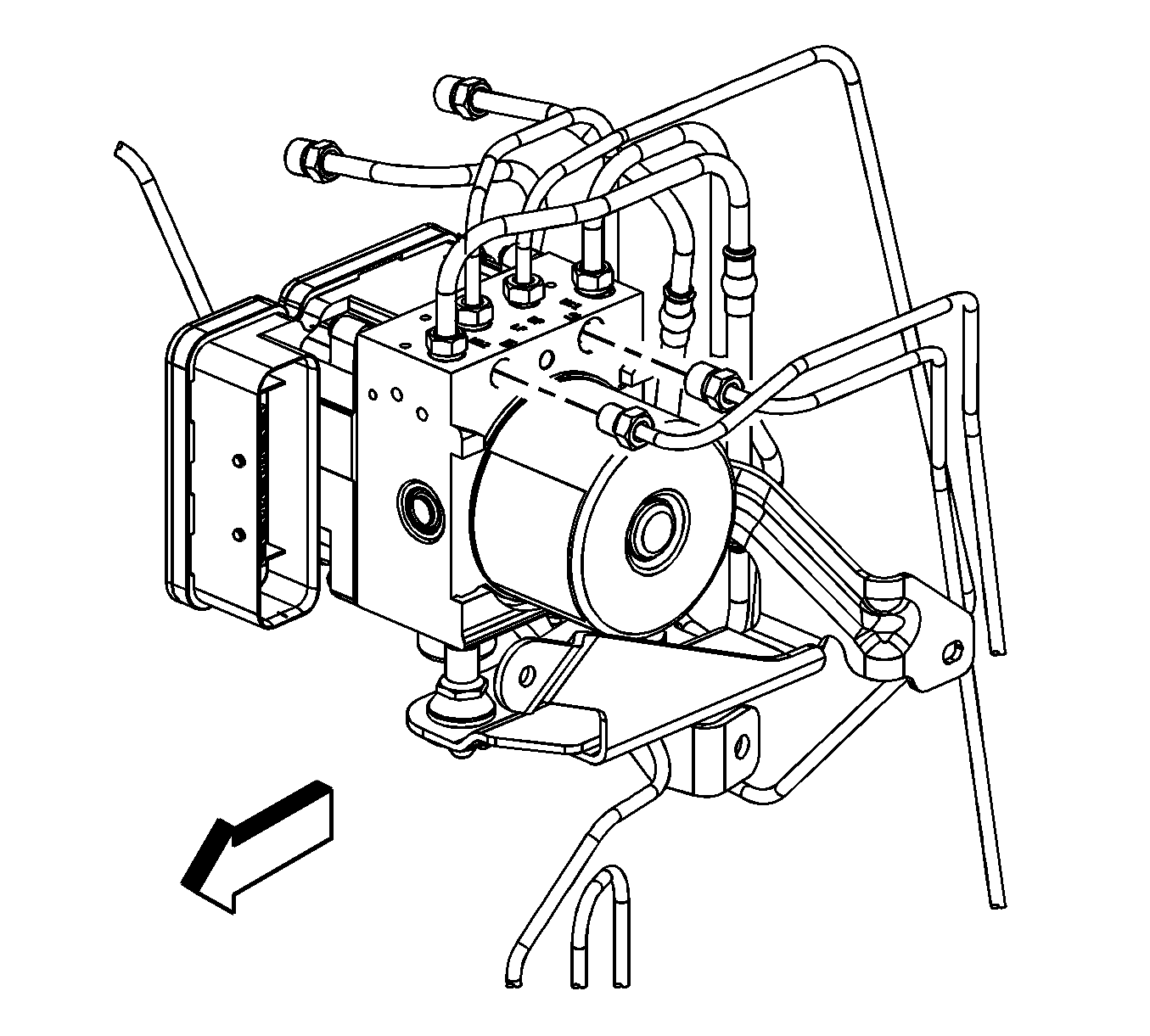
- Disconnect the rear brake line fittings from the brake pressure module.
- Raise and support the vehicle. Refer to Lifting and Jacking the Vehicle .
- Remove the EVAP canister. Refer to Evaporative Emission Canister Replacement .
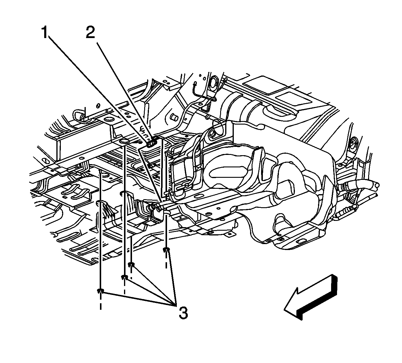
- Disconnect the fuel feed pipe quick connect fitting (2) from the fuel tank. Refer to Plastic Collar Quick Connect Fitting Service .
- Cap the fuel and EVAP lines in order to prevent system contamination.
- Disconnect the left rear brake line fitting from the brake crossover pipe.
- Disconnect the right rear brake line fitting from the rear brake hose.
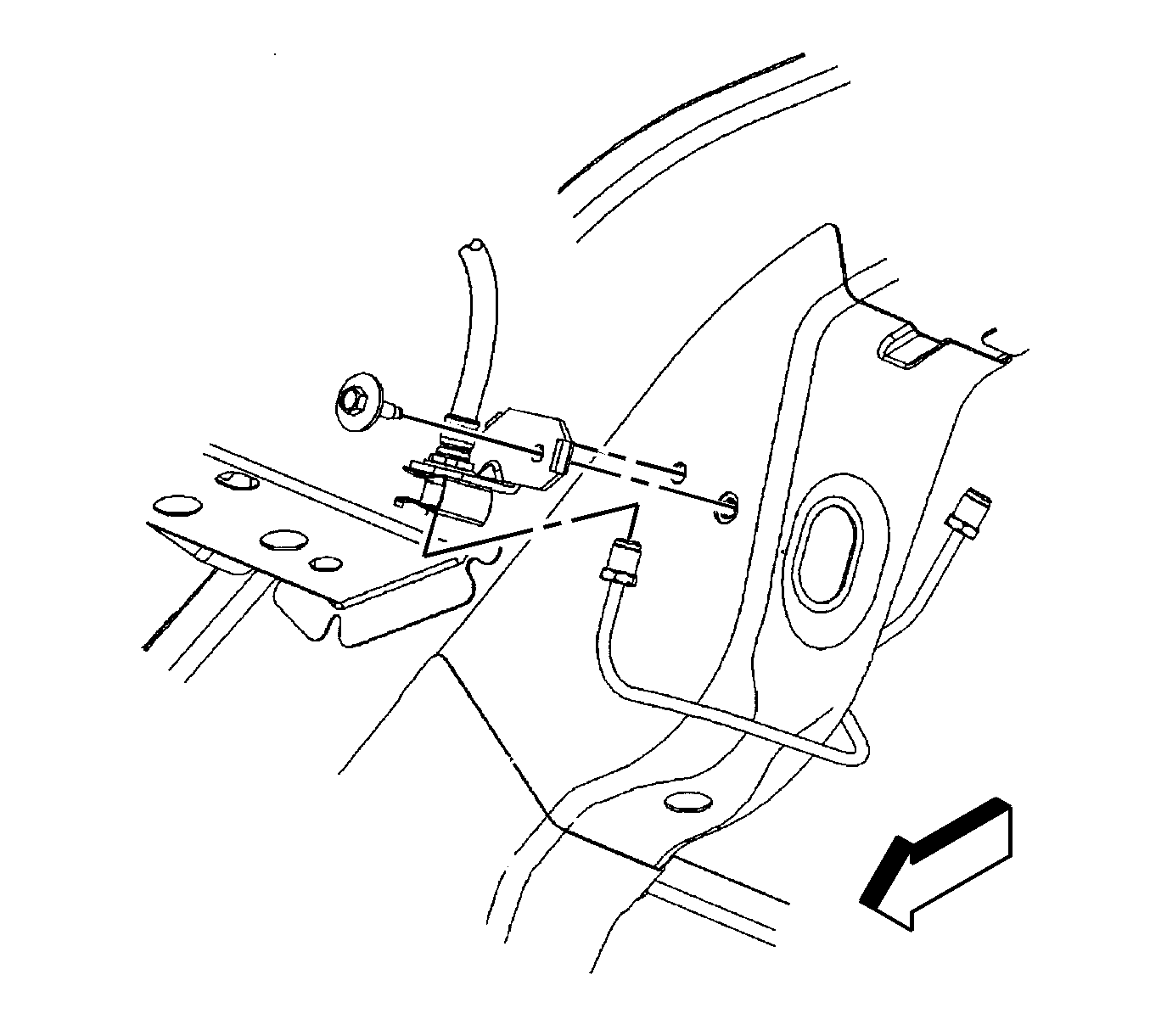
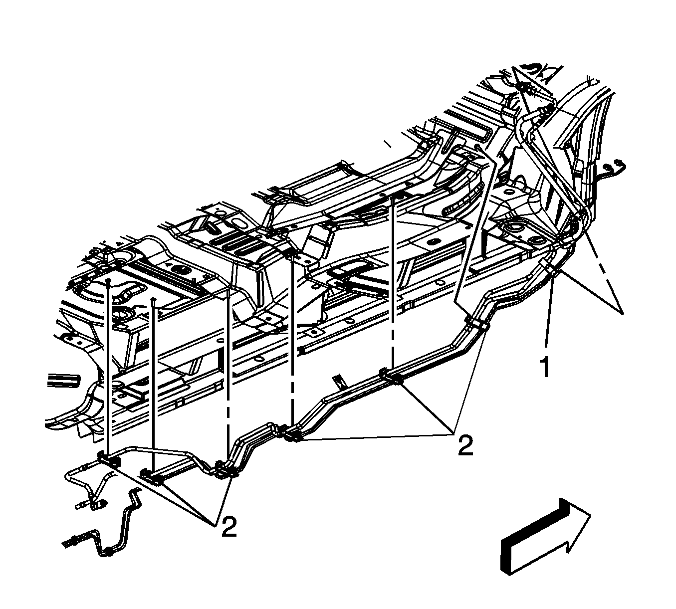
- Remove the push pin (1) from the underbody side rail hole.
- With the aid of an assistant, release the fuel/EVAP/brake pipe clips (2) from the underbody studs.
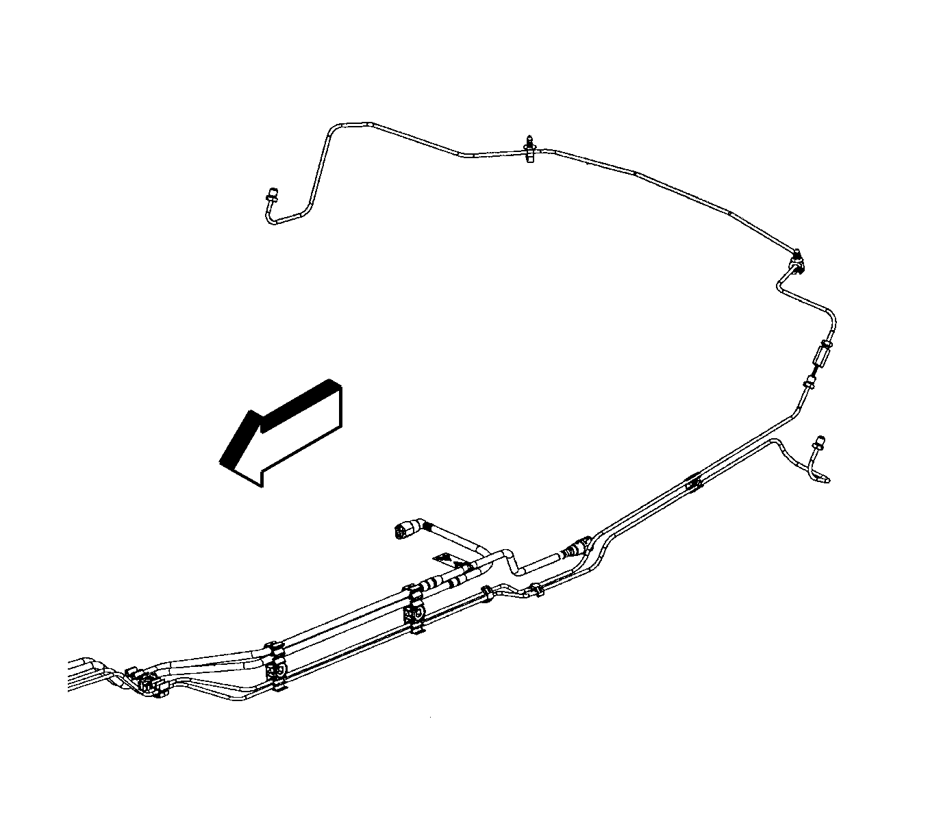
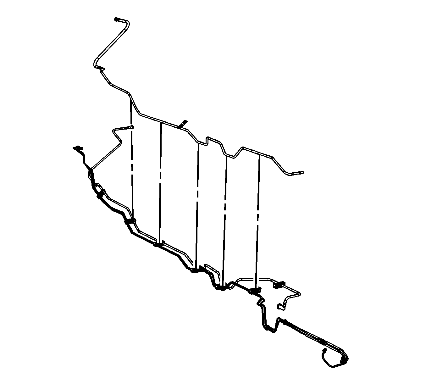
- Place the fuel/EVAP/brake pipe assembly on a clean work surface.
- Remove the fuel feed pipe from the fuel/EVAP/brake pipe assembly clips.
Installation Procedure
- Install the fuel feed pipe to the fuel/EVAP/brake pipe assembly clips.
- With the aid of an assistant, position and install the fuel/EVAP/brake pipe clips (2) to the underbody studs.
- Install the push pin (1) to the underbody side rail hole.
- Connect the right rear brake line fitting to the rear brake hose.
- Connect the left rear brake line fitting to the brake crossover pipe.
- Remove the caps from the fuel and EVAP lines.
- Connect the fuel feed pipe quick connect fitting (2) to the fuel tank. Refer to Plastic Collar Quick Connect Fitting Service .
- Install the EVAP canister. Refer to Evaporative Emission Canister Replacement .
- Lower the vehicle.
- Connect the rear brake line fittings to the brake pressure module.
- Remove the caps from the fuel and EVAP lines.
- Connect the fuel feed pipe quick connect fitting (3) to the fuel rail. Refer to Metal Collar Quick Connect Fitting Service .
- Connect the EVAP pipe quick connect fitting (3) to the EVAP purge solenoid. Refer to Plastic Collar Quick Connect Fitting Service .
- Connect the negative battery cable. Refer to Battery Negative Cable Disconnection and Connection .
- Bleed the hydraulic brake system. Refer to Hydraulic Brake System Bleeding .
- Prime the fuel system.
- Run the engine and check the system for leaks.


Notice: Refer to Fastener Notice in the Preface section.

Tighten
Tighten the fitting to 18 N·m (13 lb ft).

Tighten
Tighten the fitting to 18 N·m (13 lb ft).


Tighten
Tighten the fitting to 21 N·m (16 lb ft).

| 16.1. | Cycle the ignition ON for 5 seconds and then OFF for 10 seconds. Repeat cycling twice. |
| 16.2. | Crank the engine until it starts. The maximum starter motor cranking time is 20 seconds. |
| 16.3. | If the engine does not start, repeat the above steps. |
