- Remove the instrument panel left lower closeout panel. Refer to
Instrument Panel Insulator Panel Replacement - Left Side .
- Remove the knee bolster. Refer to
Knee Bolster Replacement .
Caution: Improper cruise control release switch adjustment may cause brake damage such as brake drag, heat buildup and excessive brake lining wear.

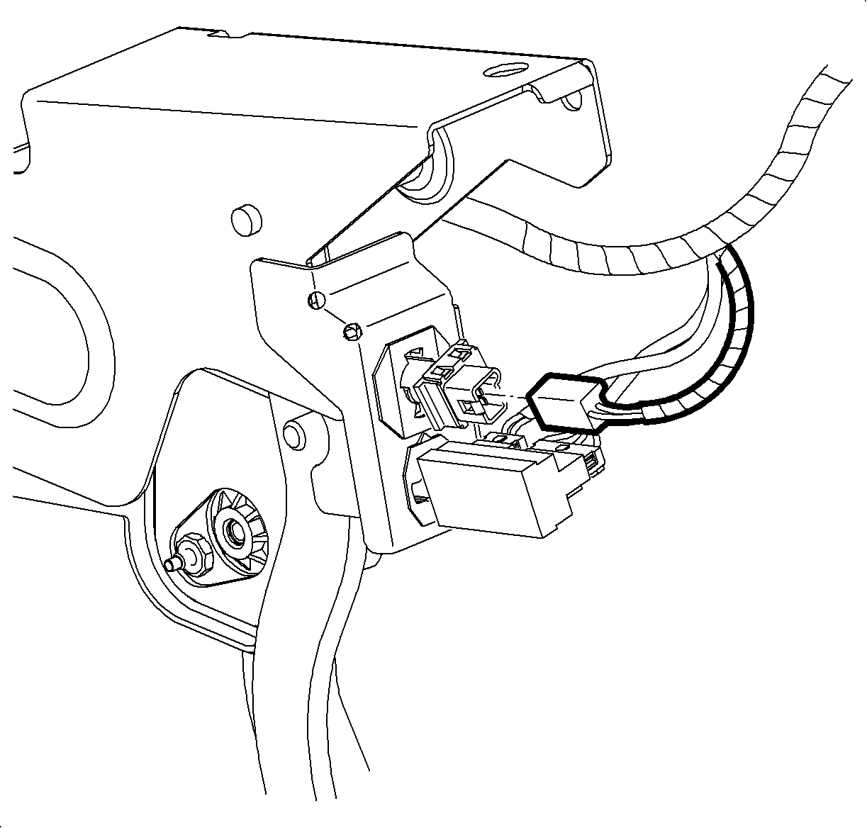
- Disconnect the cruise brake switch harness connector.
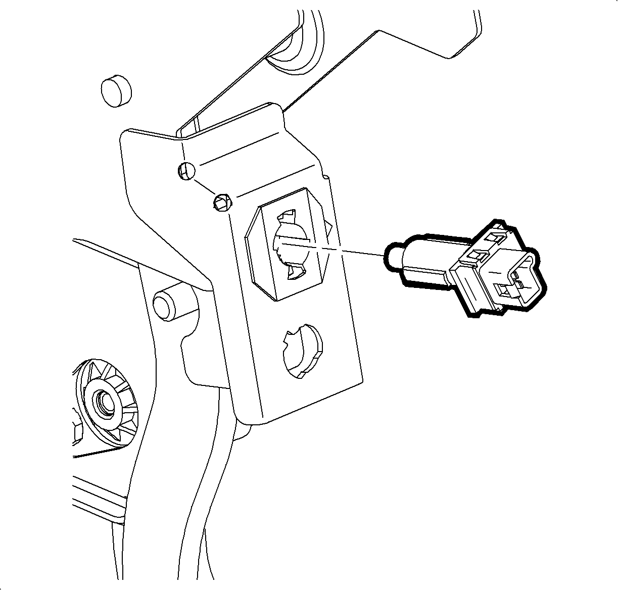
- Rotate the cruise brake switch counterclockwise and remove the cruise brake switch from the switch retainer.
Note: Do not depress the brake pedal assembly during the brake switch installation. Depressing the brake pedal will cause a brake drag condition.

- Install the cruise brake switch.
| • | Position the switch into the retainer with the electrical connector index notch pointing to the 1 o'clock position. |
| • | Slide the switch in the retainer until the plunger is fully depressed into the barrel. |
| • | Rotate the switch clockwise until the travel stop has been reached, approximately 60 degrees. |
| • | Inspect the cruise brake switch to ensure the switch is properly locked into the switch retainer with the cruise brake switch electrical connector index notch pointing to the 3 o'clock position. |

- Connect the cruise brake switch harness connector.
- Install the knee bolster. Refer to
Knee Bolster Replacement .
- Install the instrument panel left lower closeout panel. Refer to
Instrument Panel Insulator Panel Replacement - Left Side .
- Use the scan tool to monitor CRUISE BRAKE SWITCH in the engine control module (ECM) General Information data table, while depressing and releasing the brake pedal. Verify the APPLIED and RELEASED states read correctly.


