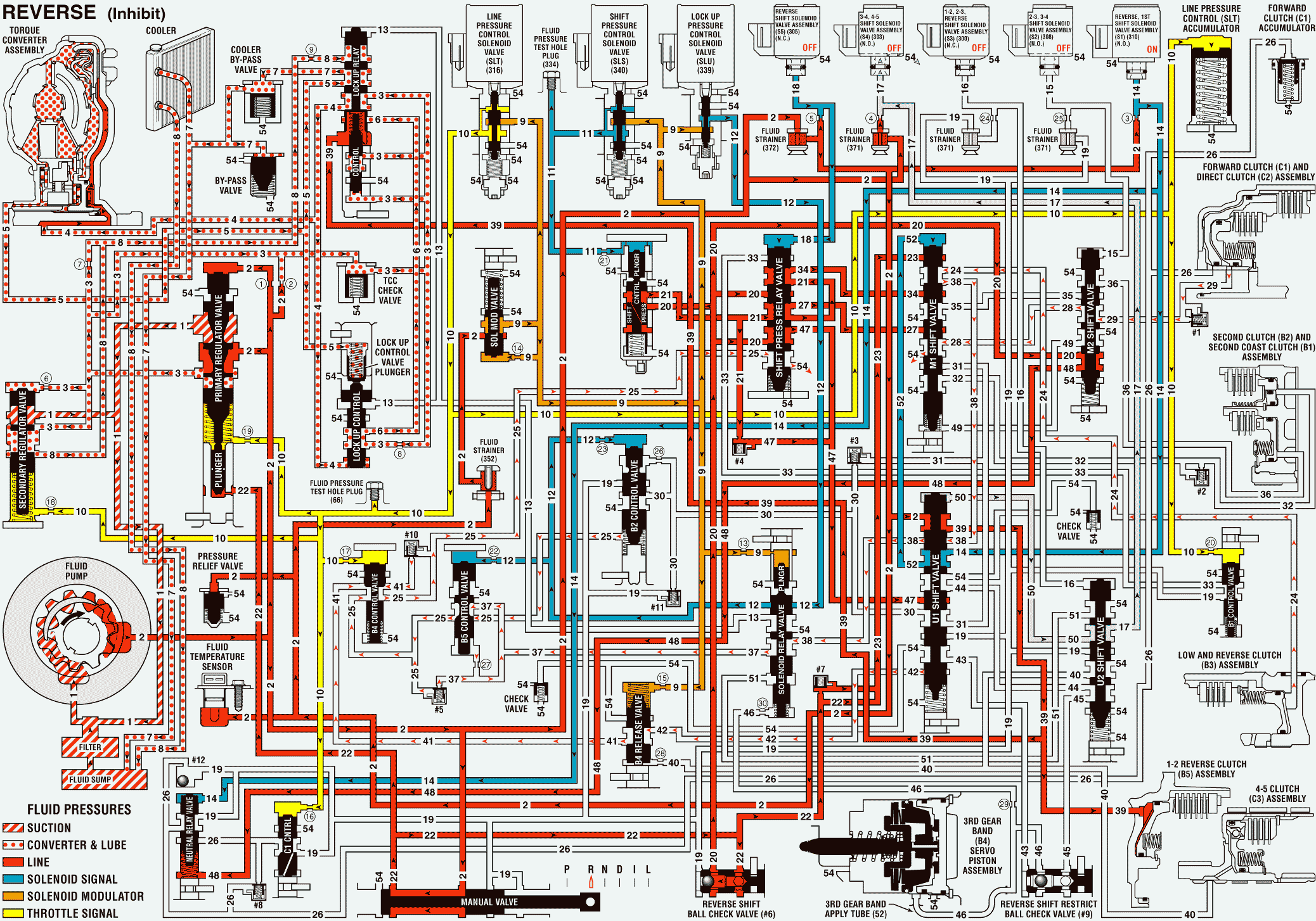
If vehicle speed becomes greater than 12 km/h (7 mph) while the transmission is operating in REVERSE, the TCM commands the following changes to the transmission's hydraulic and electrical systems in order to inhibit reverse operation and prevent damage to the transmission.
LOW AND REVERSE CLUTCH (B3) ASSEMBLY RELEASES
Reverse, 1st Shift Solenoid (SS) Valve Assembly (S1)
The reverse, 1st SS valve assembly is energized, causing fluid pressure to build-up in the S1 signal (14) fluid circuit.
U1 Shift Valve
S1 signal (14) fluid is routed to the U1 shift valve and passes through the valve into the reverse inhibit (52) fluid circuit.
M1 Shift Valve
Reverse inhibit (52) fluid is routed to the M1 shift valve and applies the valve against spring force.
Reverse Shift Solenoid (SS) Valve Assembly (S5)
The reverse SS valve assembly is de-energized, causing fluid pressure to build-up in the S5 signal (18) fluid circuit.
Shift Pressure Relay Valve
S5 signal (18) fluid is routed to the shift pressure relay valve and applies the valve against spring force.
Low and Reverse Clutch (B3) Assembly
When the M1 shift valve is shifted to the applied position, reverse clutch (23) fluid is blocked and low and reverse clutch (24) fluid exhausts through the valve allowing the low and reverse clutch assembly to release.
Shift Pressure Relay Valve
Exhausting low and reverse clutch (24) fluid is routed into the B5 control 2 (38) fluid passage at the M1 shift valve, the B5 control 1 (37) fluid passage at the solenoid relay valve, the reverse control (25) fluid passage at the B5 control valve, and on to the shift pressure relay valve where it exhausts.
1-2, 2-3, Reverse Shift Solenoid (SS) Valve Assembly (S3)
The 1-2, 2-3, reverse SS valve assembly is de-energized. However, because there is no fluid supplied to the circuit, the 1-2, 2-3, reverse SS valve assembly has no effect in REVERSE INHIBIT.
DIRECT CLUTCH (C2) ASSEMBLY RELEASES
Direct Clutch (C2) Assembly
When the M1 shift valve is shifted to the applied position, direct clutch feed 1 (27) fluid is blocked and direct clutch (29) fluid pressure exhausts, allowing the direct clutch assembly to release.
M2 Shift Valve
Exhausting direct clutch (29) fluid passes through the M2 shift valve into the direct clutch feed 2 (28) fluid circuit and on to the M1 shift valve where it exhausts.
PASSAGES
- SUCTION
- LINE
- CONVERTER FEED
- RELEASE
- APPLY
- EXHAUST ENABLE
- COOLER
- LUBE
- SOLENOID MODULATOR
- THROTTLE SIGNAL (SLT)
- SHIFT CONTROL (SLS)
- LOCK UP CONTROL (SLU)
- TCC SIGNAL
- S1 SIGNAL
- S2 SIGNAL
- S3 SIGNAL
- S4 SIGNAL
- S5 SIGNAL
- DRIVE
- DRIVE OR REVERSE
- REGULATED DRIVE OR REVERSE
- REVERSE
- REVERSE CLUTCH
- LOW AND REVERSE CLUTCH
- REVERSE CONTROL
- FORWARD CLUTCH
- DIRECT CLUTCH FEED 1
- DIRECT CLUTCH FEED 2
- DIRECT CLUTCH
- B2 CONTROL 1
- B2 CONTROL 2
- SECOND CLUTCH
- B1 CONTROL 1
- B1 CONTROL 2
- B1 CONTROL 3
- SECOND COAST CLUTCH
- B5 CONTROL 1
- B5 CONTROL 2
- 1-2 REVERSE (B5) CLUTCH
- 4-5 CLUTCH
- B4 CONTROL
- B4 RELEASE
- SERVO RELEASE
- SERVO FEED
- SERVO APPLY
- 3RD GEAR BAND APPLY
- PN12345
- PRN15
- 234NCON
- 345 ENABLE
- 45 ENABLE
- REVERSE INHIBIT
- VENT
- EXHAUST
- SUMP
- VOID
- TORQUE CONVERTER SEAL DRAINBACK
Reverse - Inhibit

