For 1990-2009 cars only
Removal Procedure
- Raise and support the vehicle. Refer to Lifting and Jacking the Vehicle.
- Remove the rear tire and wheel assembly. Refer to Tire and Wheel Removal and Installation.
- Remove the brake rotor. Refer to Rear Brake Rotor Replacement.
- Remove the wheel speed sensor. Refer to Rear Wheel Speed Sensor Replacement.
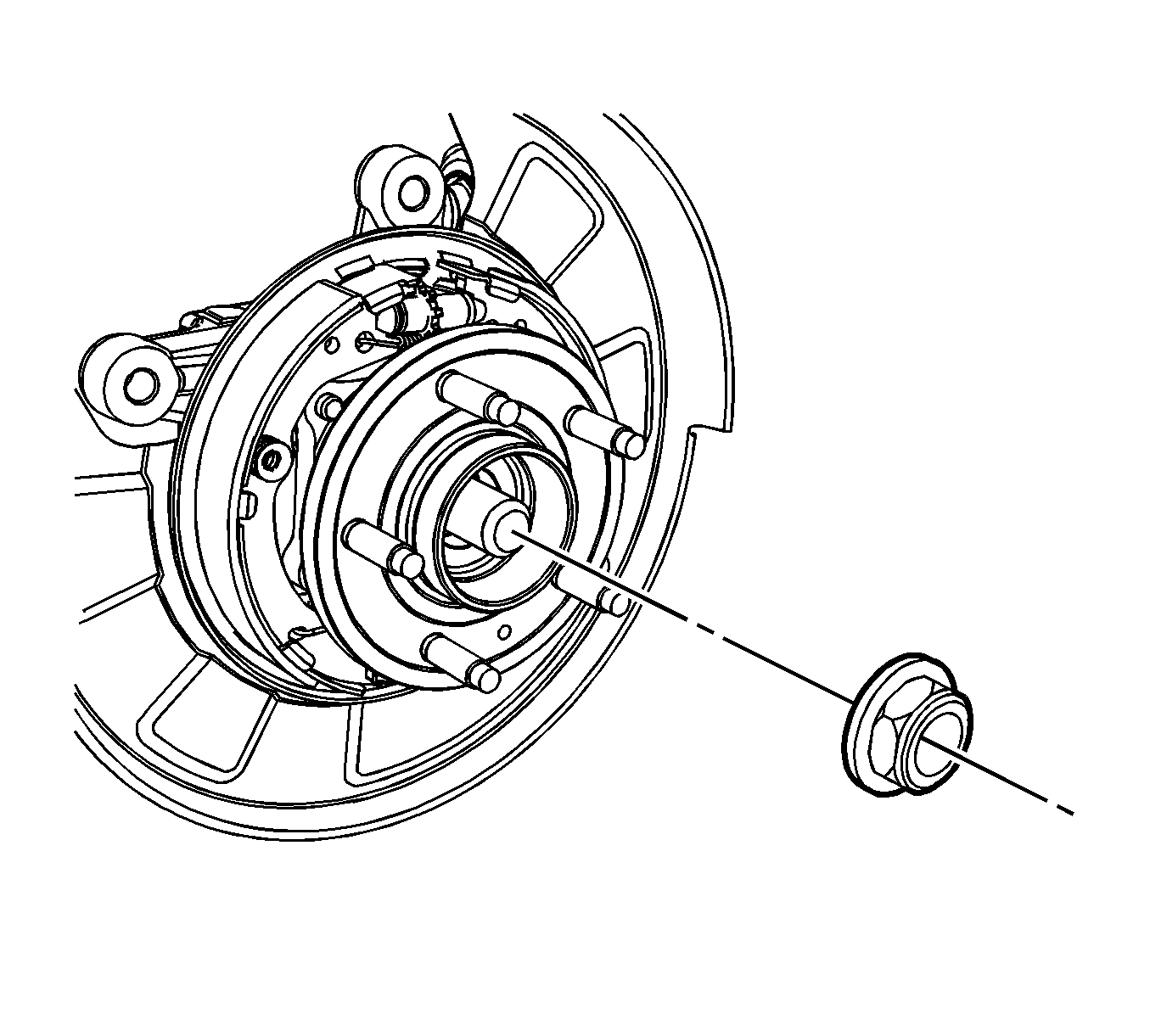
- If equipped with all wheel drive (AWD), remove the rear wheel driveshaft nut.
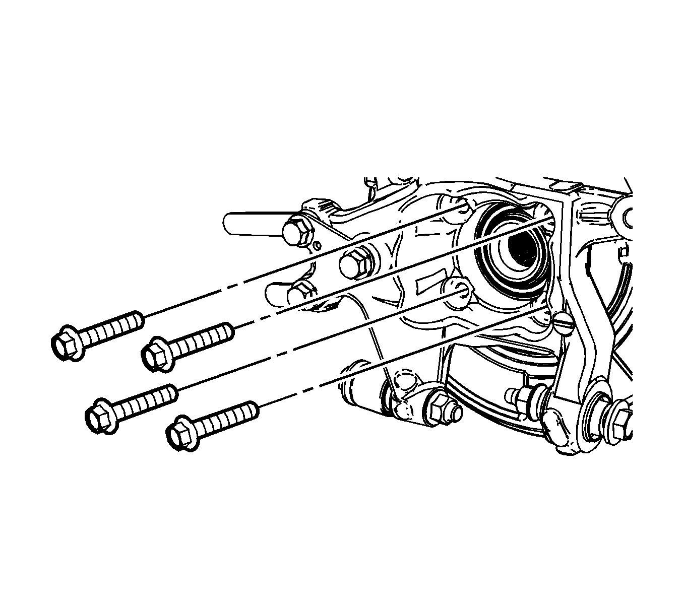
- Remove the 4 wheel bearing bolts.
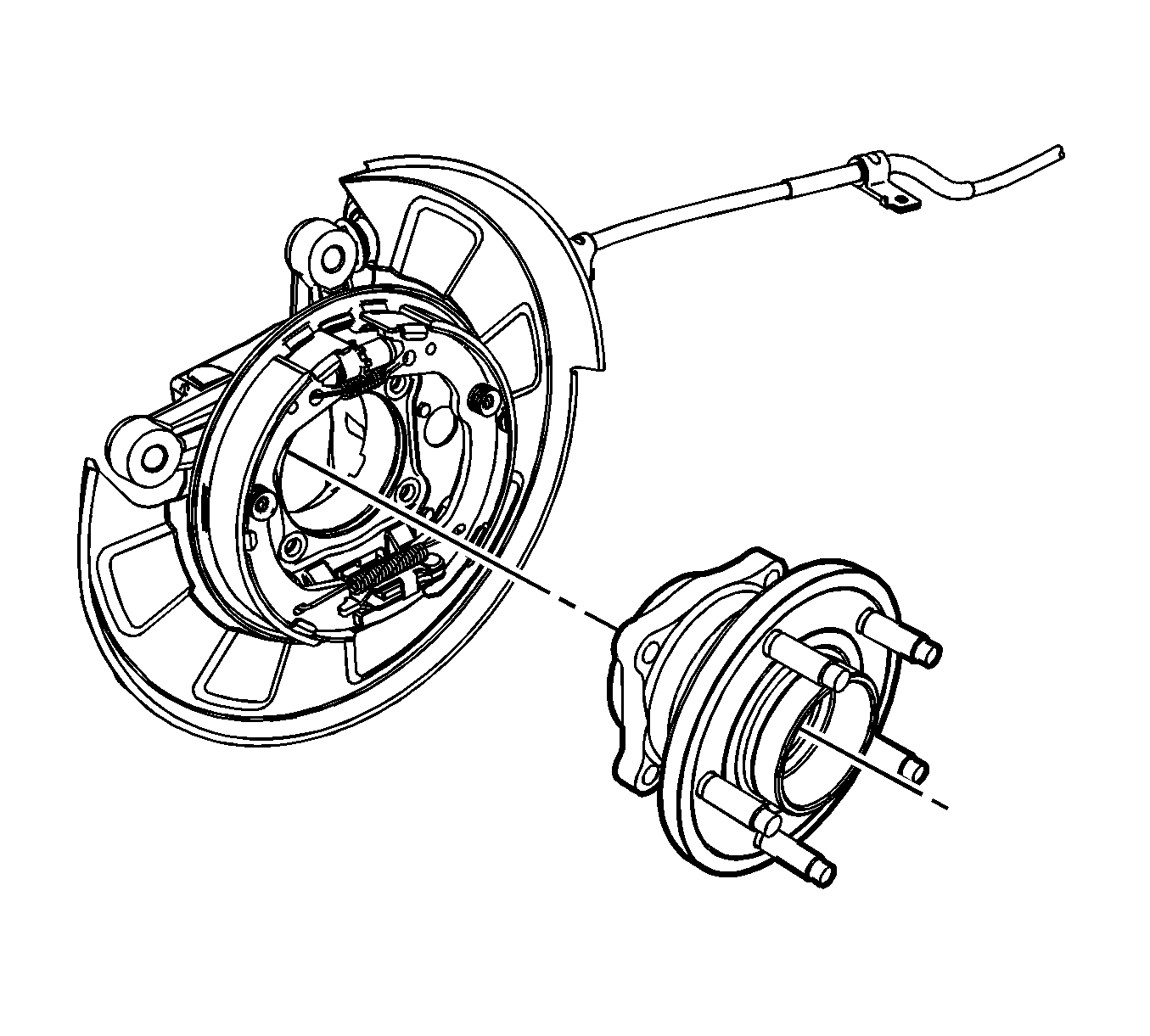
- Remove the wheel bearing from the knuckle.

Note: The splash shield and park brake assembly are supported to the knuckle between the wheel bearing mounting bolts and the wheel bearing. Care should be taken to support these items while the wheel bearing is being replaced.


Installation Procedure
- Position the wheel bearing to the knuckle.
- Install the 4 wheel bearing bolts and tighten the bolts to 75 N·m (55 lb ft).
- If equipped with AWD, install the rear wheel driveshaft nut and tighten the nut to 205 N·m (151 lb ft).
- Install the wheel speed sensor. Refer to Rear Wheel Speed Sensor Replacement.
- Install the brake rotor. Refer to Rear Brake Rotor Replacement.
- Install the rear tire and wheel assembly. Refer to Tire and Wheel Removal and Installation.
- Lower the vehicle.

Caution: Refer to Fastener Caution in the Preface section.


