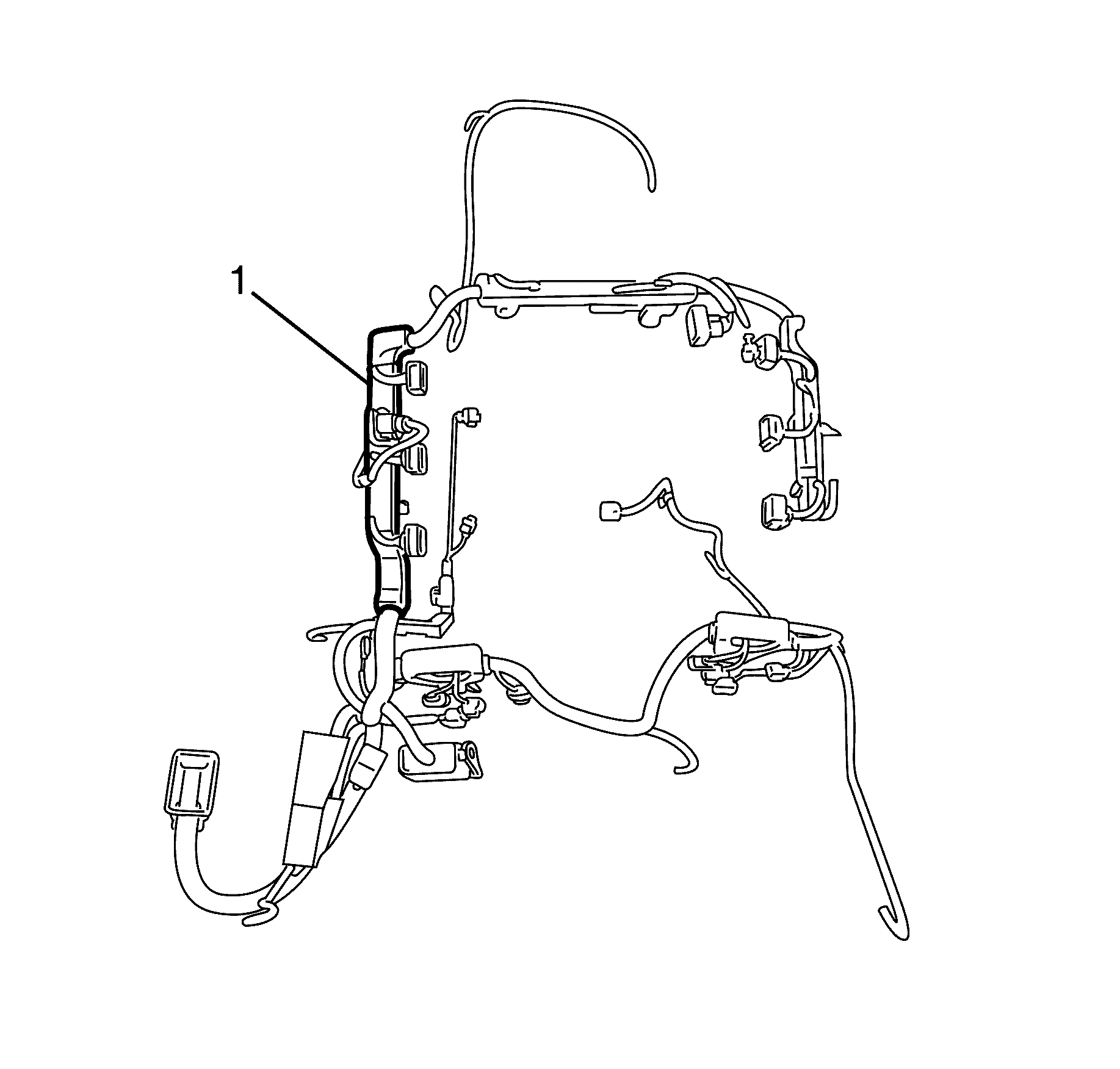
- Remove the engine covers. Refer to Engine Cover Replacement .
- Disconnect the right camshaft position sensors electrical connectors (1).
- Disconnect the right bank intake and exhaust camshaft position actuator valve electrical connectors (5).
- Detach the engine wiring harness to cylinder head retaining lug (3).
- Detach the engine wiring harness bracket (2) from the right bank camshaft cover (4).
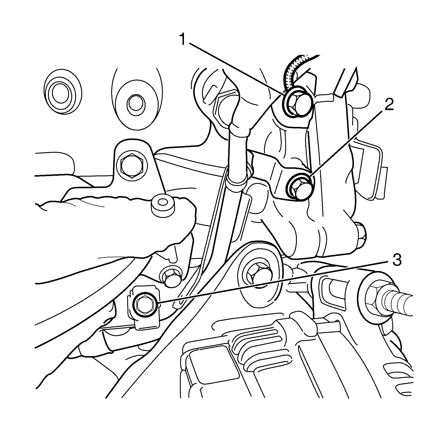
- Remove the engine wiring harness ground to right bank cylinder head front retaining bolt (1).
- Remove the engine wiring harness bracket to right bank cylinder head retaining bolt (2).
- Remove the engine wiring harness bracket to cylinder block retaining bolt (3).
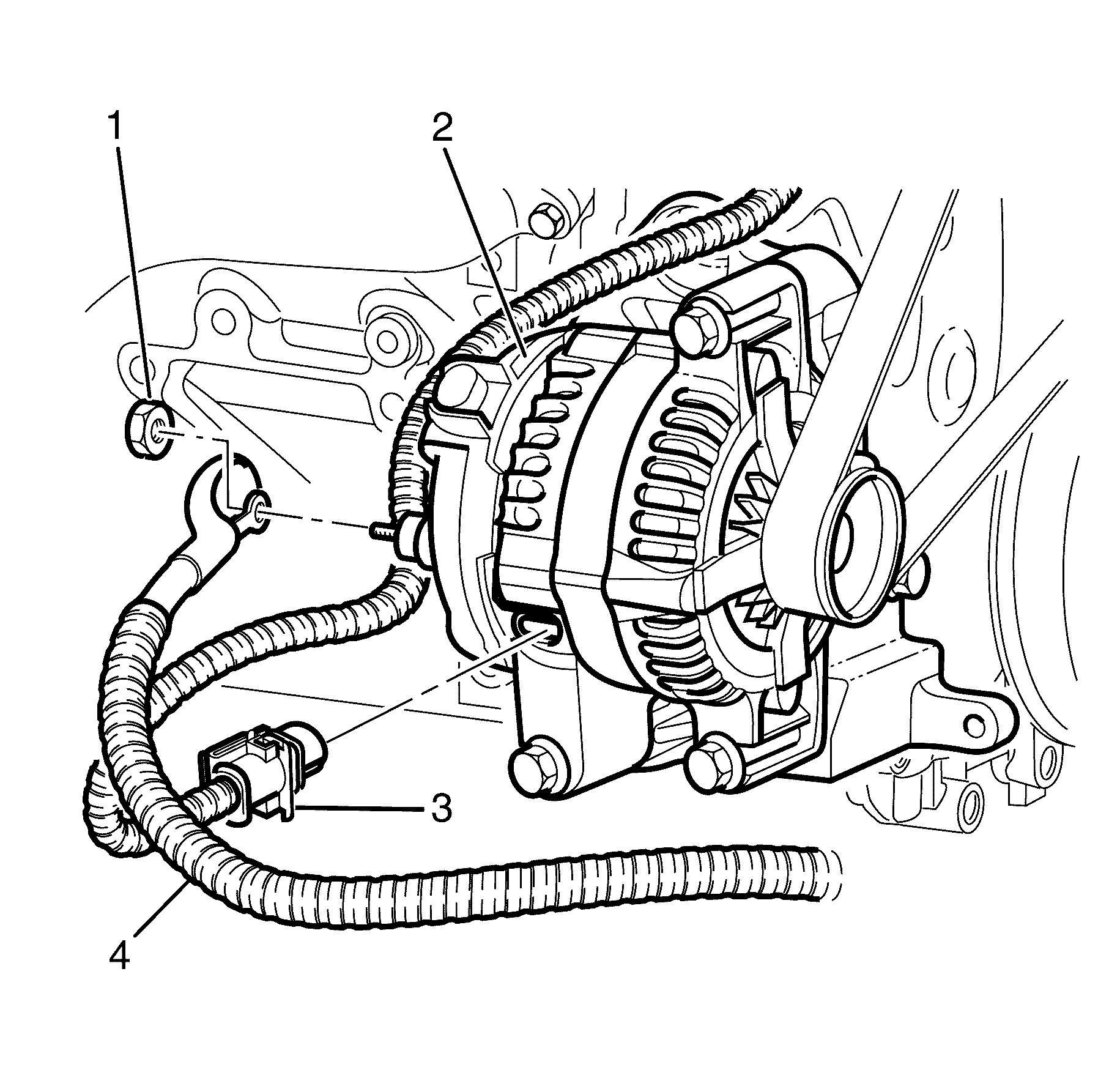
- Remove the battery positive cable to alternator retaining nut (1).
- Disconnect the battery positive cable (2) from the alternator (3).
- Disconnect the alternator battery harness connector (4).
- Remove the alternator and mounting bracket. Refer to Generator Removal .
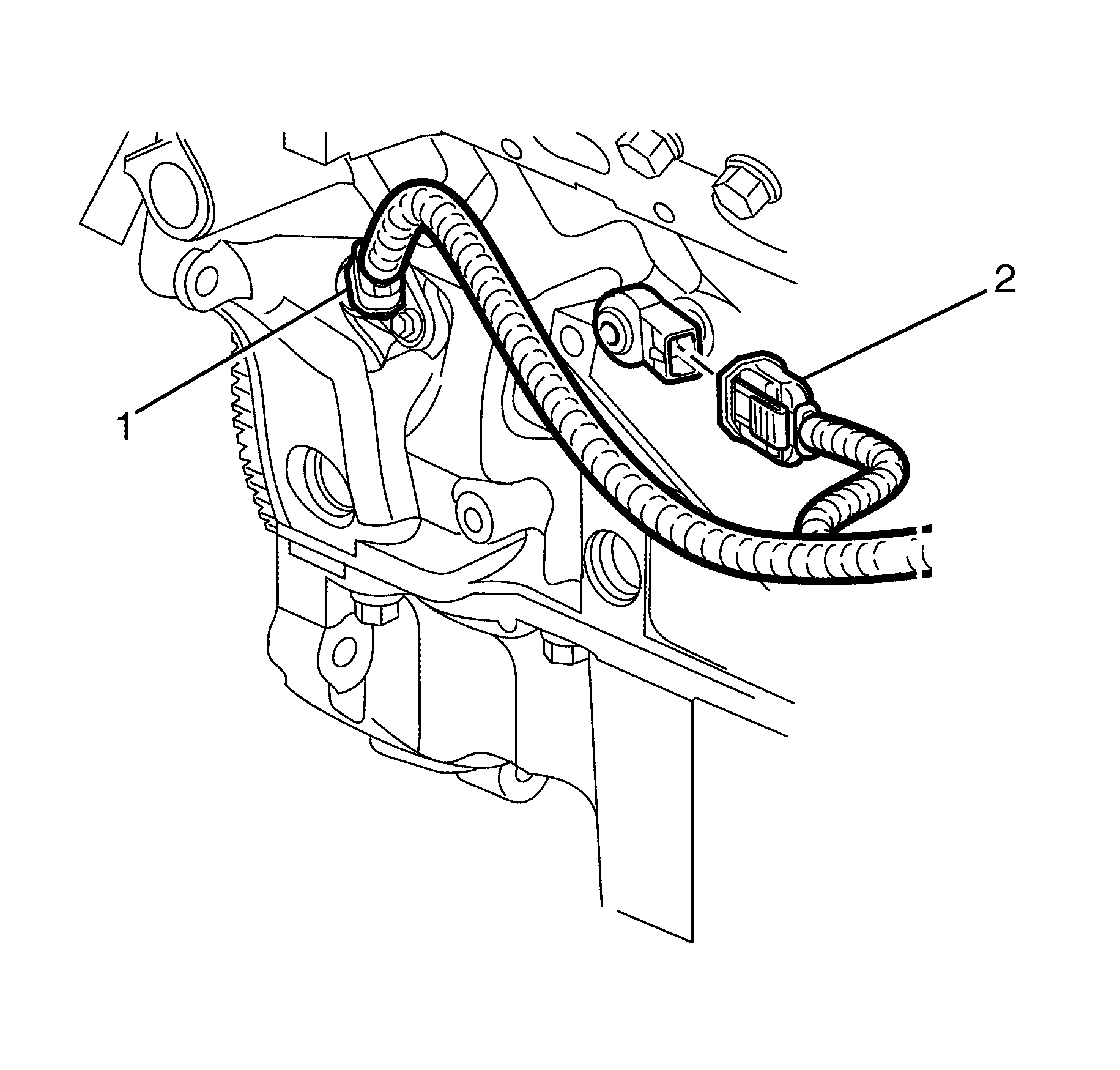
- Disconnect the right bank knock sensor electrical connector (2).
- Disconnect the crankshaft position sensor electrical connector (1).
- Disconnect the right bank ignition coil electrical connectors (2).
- Remove the engine wiring harness ground to right bank cylinder head rear retaining bolt (4).
- Detach the engine wiring harness (1) from the right bank camshaft cover (3).
- Disconnect the right hand Heated Oxygen Sensor 1 electrical connector (2) if still connected after engine removal.
- Disconnect the main transmission electrical connector (3).
- Disconnect the vehicle speed sensor electrical connector (4)
- Disconnect the park/neutral switch electrical connector (1).
- Disconnect the right hand Heated Oxygen Sensor 1 electrical connector (1) if still connected after engine removal.
- Disconnect the main transmission electrical connector (2).
- Disconnect the right hand Heated Oxygen Sensor 1 electrical connector (1) if still connected after engine removal.
- Disconnect the reverse switch assembly electrical connector (2).
- Disconnect the left hand Heated Oxygen Sensor 1 electrical connector (3) if still connected after engine removal.
- Detach the left hand Heated Oxygen Sensor 1 electrical harness (1) from the engine wiring harness bracket (2).
- Remove the engine wiring harness bracket to cylinder head rear retaining bolts (1).
- Disconnect the Intake Manifold Runner Control (IMRC) electrical connector (1).
- Disconnect the injector harness electrical connector (2).
- Disconnect the purge solenoid electrical connector (3).
- Remove the engine cover bracket to cylinder head retaining bolt (2).
- Remove the engine cover bracket (1).
- Disconnect the left bank ignition coil electrical connectors (2).
- Remove the engine wiring harness ground to left bank cylinder head retaining bolt (5).
- Disconnect the coolant temperature sensor electrical connector (6).
- Disconnect the oil pressure sensor electrical connector (7).
- Detach the engine wiring harness bracket (1) from the right bank camshaft cover lugs (3) and position aside.
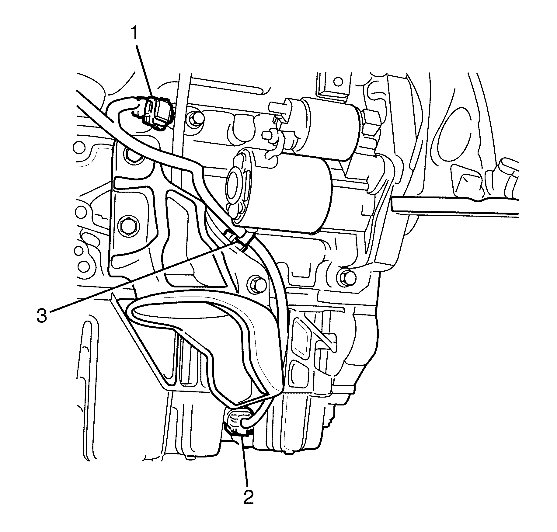
- Disconnect the starter motor electrical connector (1).
- Disconnect the battery positive cable (2) from the starter motor (3).
- Remove the battery positive cable to starter motor terminal retaining nut (1).
- Disconnect the left bank knock sensor electrical connector (1).
- Disconnect the oil level sensor electrical connector (2).
- Detach the engine wiring harness to cylinder block retaining lug (3).
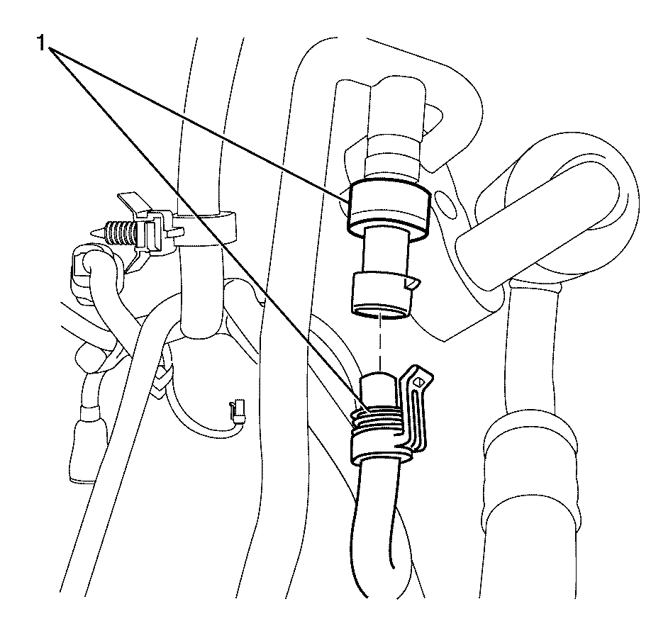
- Disconnect the A/C pressure transducer electrical connector (1).
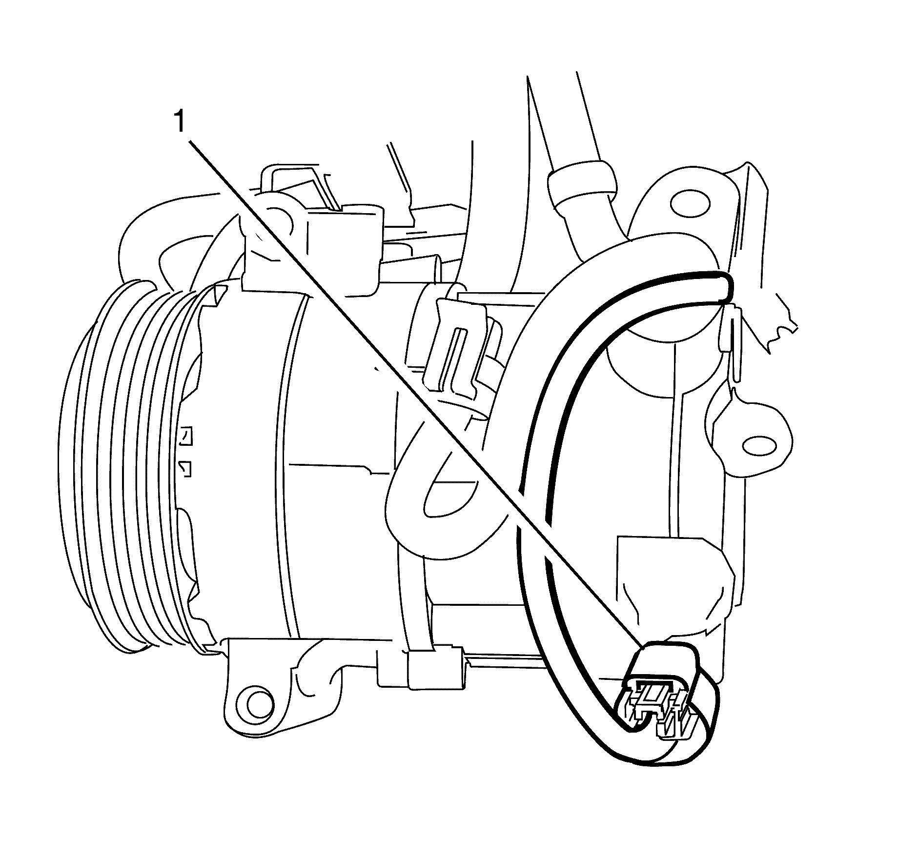
- Disconnect the A/C compressor electrical connector (1).
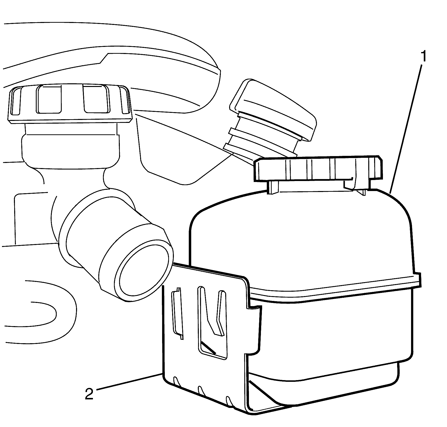
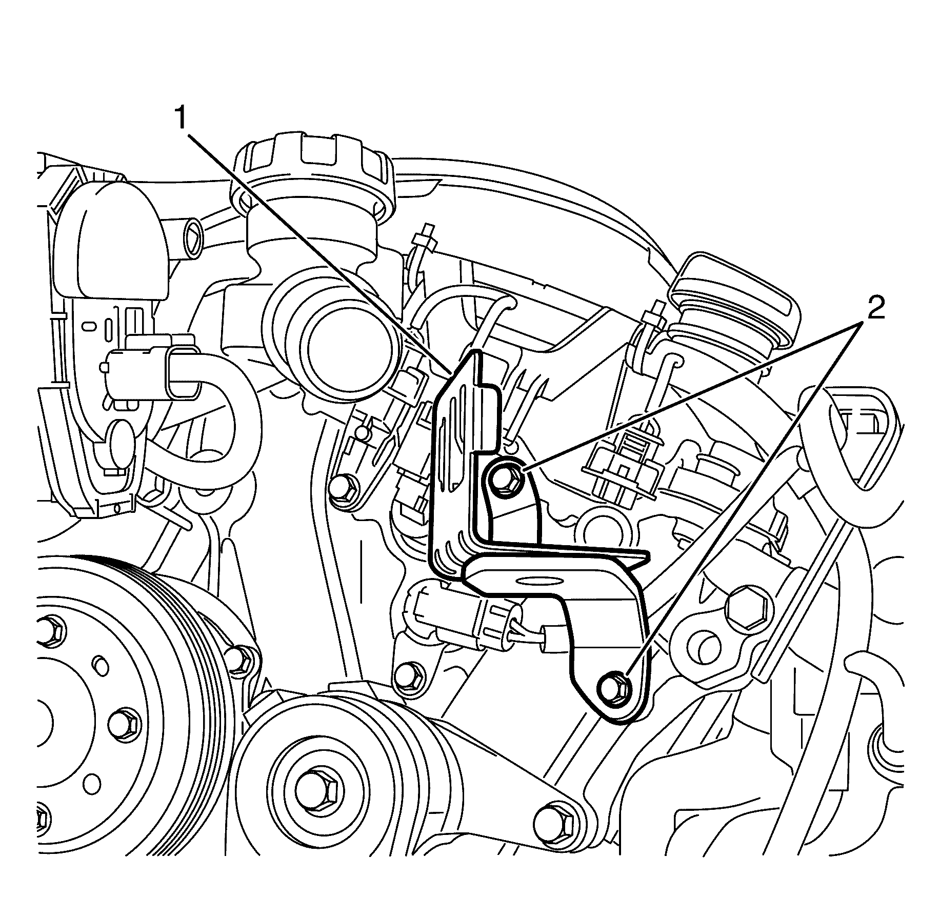
- Separate power steering fluid reservoir (1) from the power steering fluid reservoir bracket (2).
- Reposition and secure the power steering fluid reservoir away from the power steering fluid reservoir (1) bracket (2).
- Remove the power steering fluid reservoir bracket to engine front cover retaining bolts (2).
- Remove the power steering fluid reservoir bracket (1).
- Disconnect the left camshaft position sensors electrical connectors (4).
- Disconnect the left bank intake and exhaust camshaft position actuator valve electrical connectors (5).
- Disconnect the throttle position sensor electrical connector (1).
- Detach the engine wiring harness bracket (2) from the left bank camshaft cover (3).
- Remove the engine wiring harness (1).
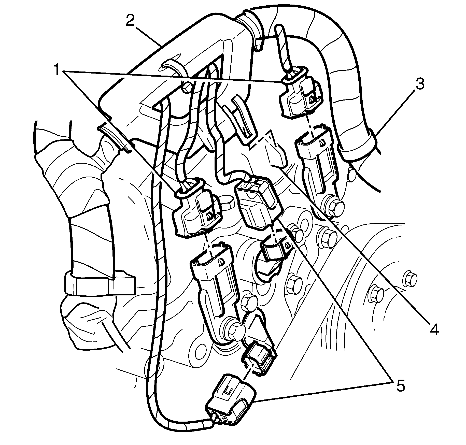
Important: LE0 and LW2 engines only have an intake camshaft position actuator valve.
Important: Use a suitable tool to detach the engine wiring harness bracket (2) from the locating clip lug on the right bank camshaft cover (4) then slide the engine wiring harness bracket (2) upwards to detach from the right bank camshaft cover (4).
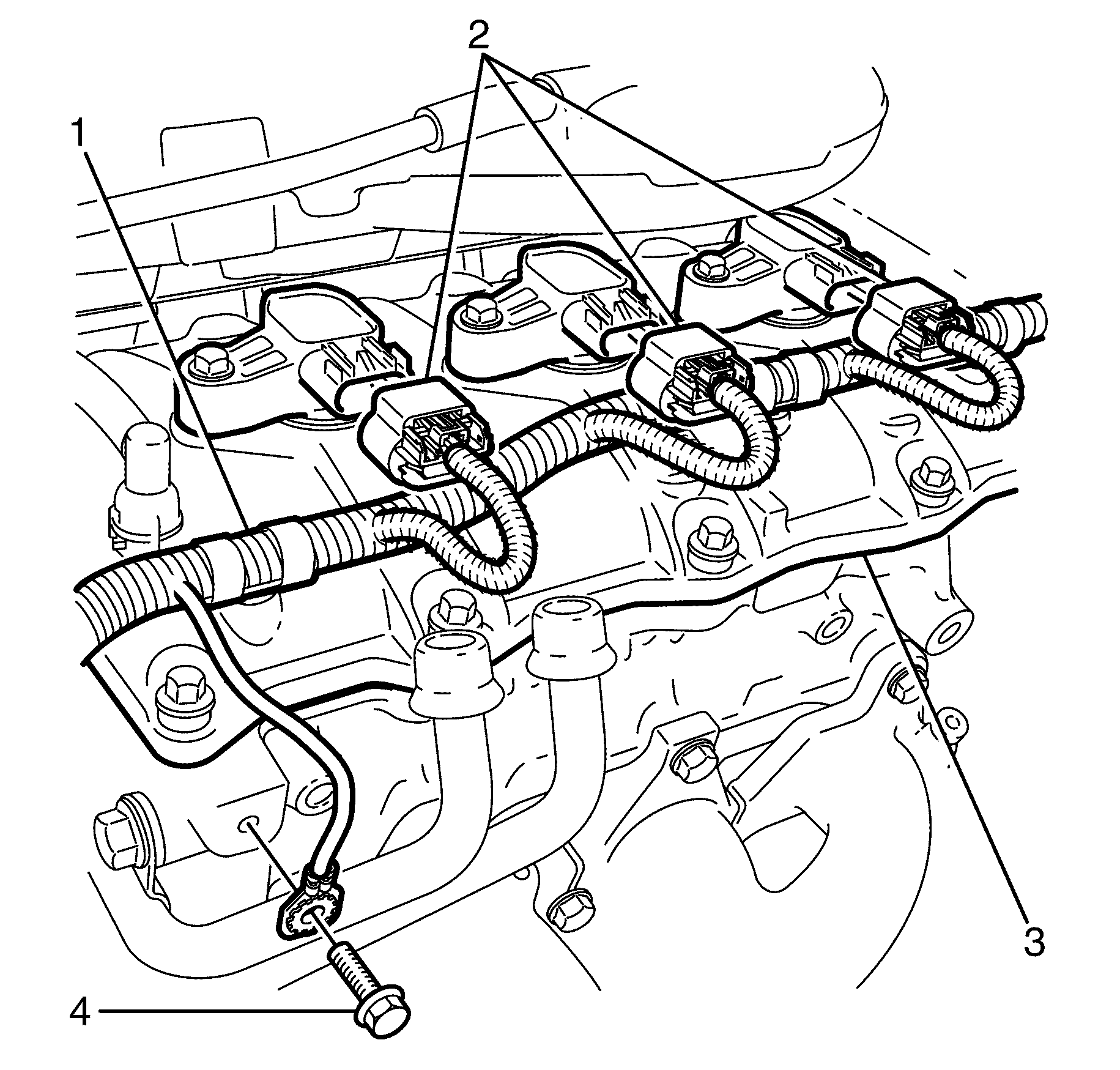
Important: Use a suitable tool to detach the engine wiring harness (1) clips from the right bank camshaft cover (4).
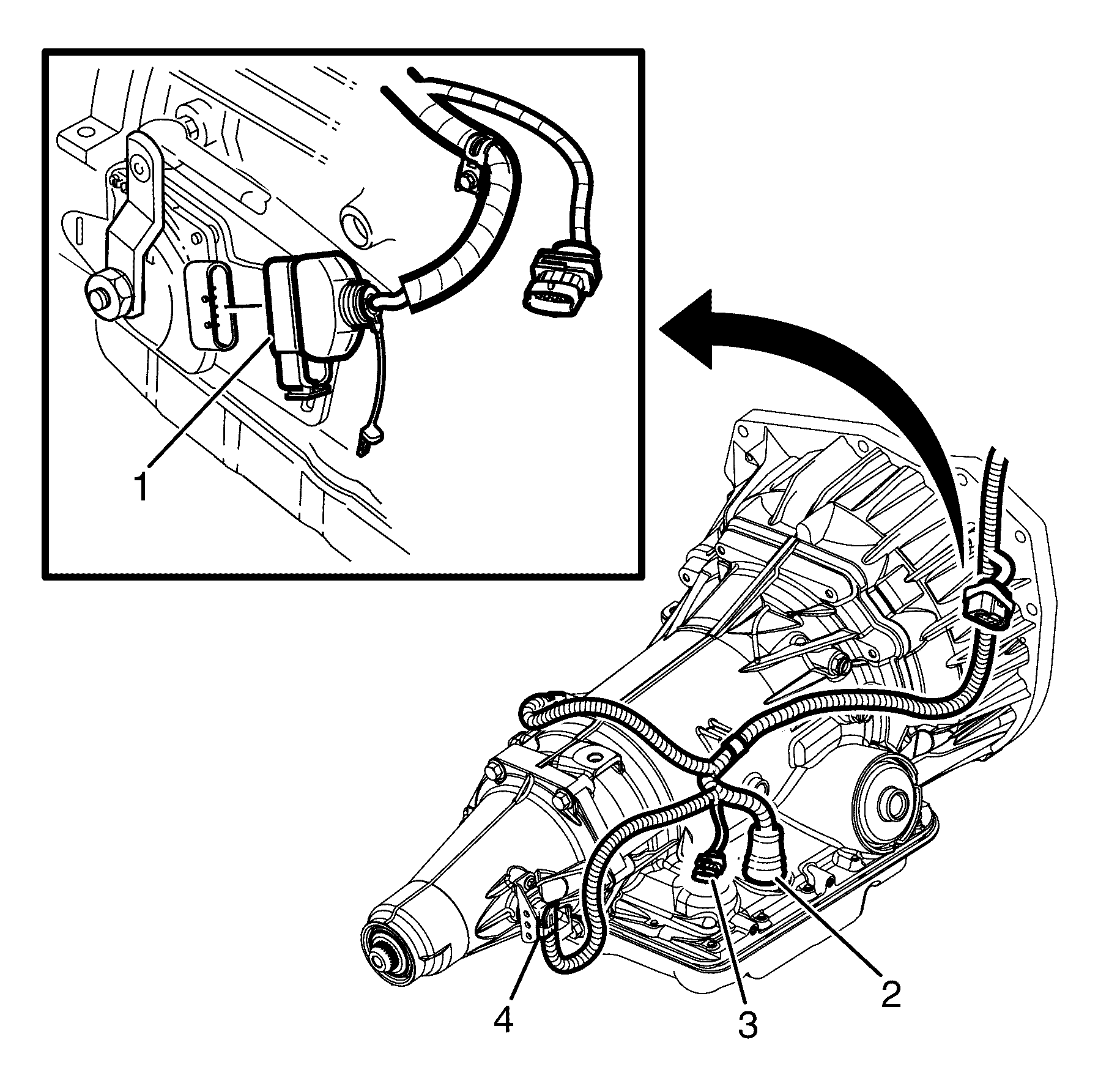
Important: Steps 19 - 22 refer to the 4L60E 4 speed automatic transmission only
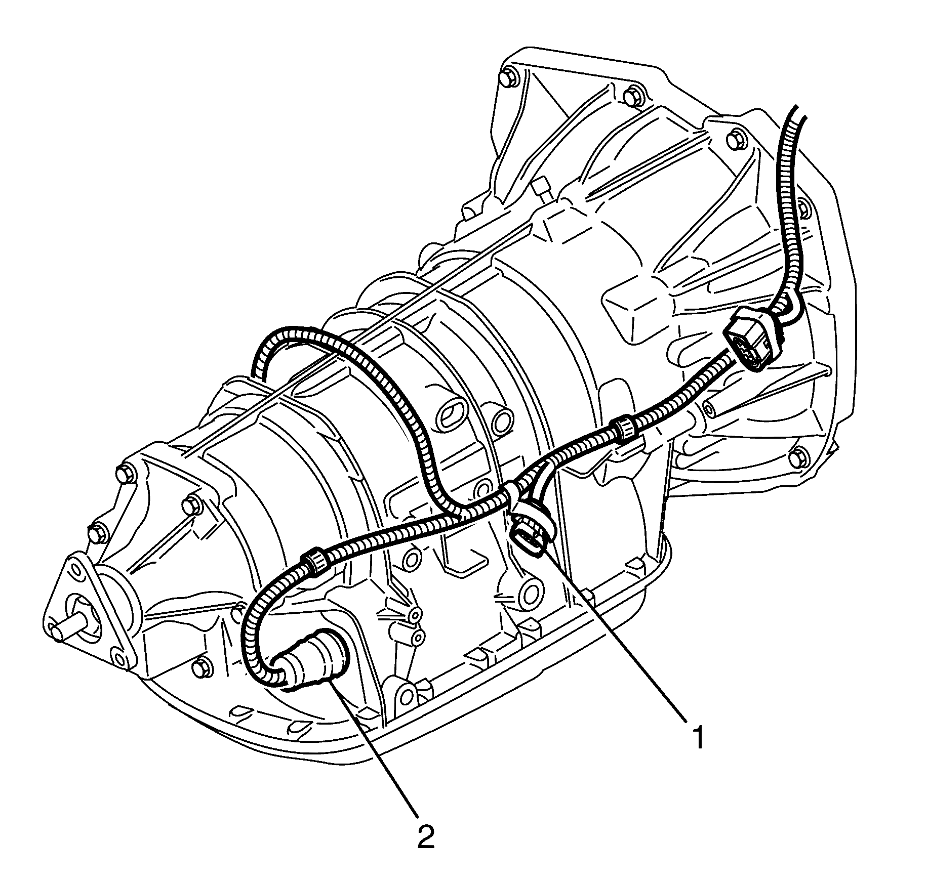
Important: Steps 24 and 25 refer to the 5L40E 5 speed automatic transmission only.
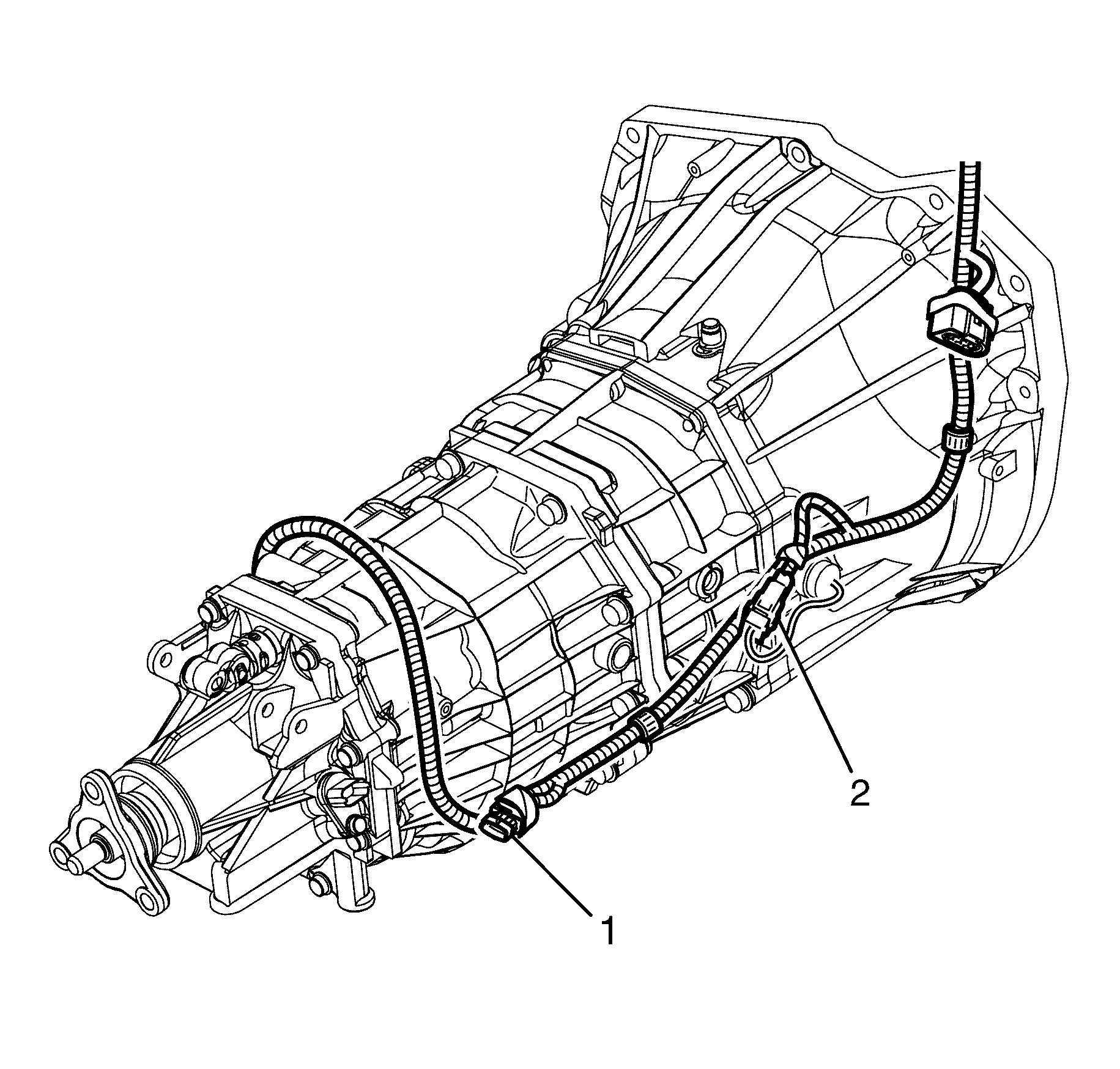
Important: Steps 27 and 28 refer to the D173 6 speed manual transmission only.
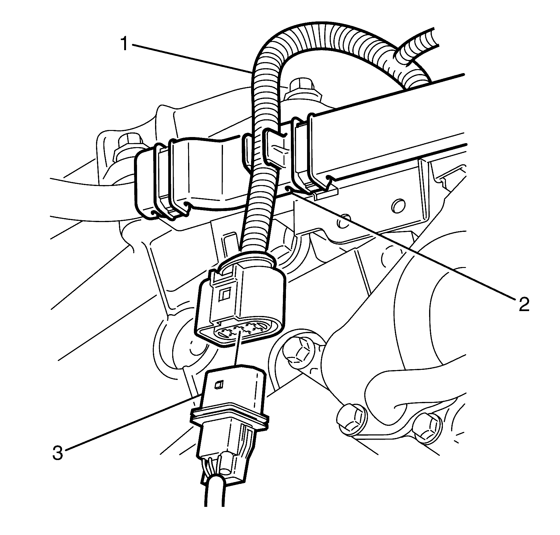
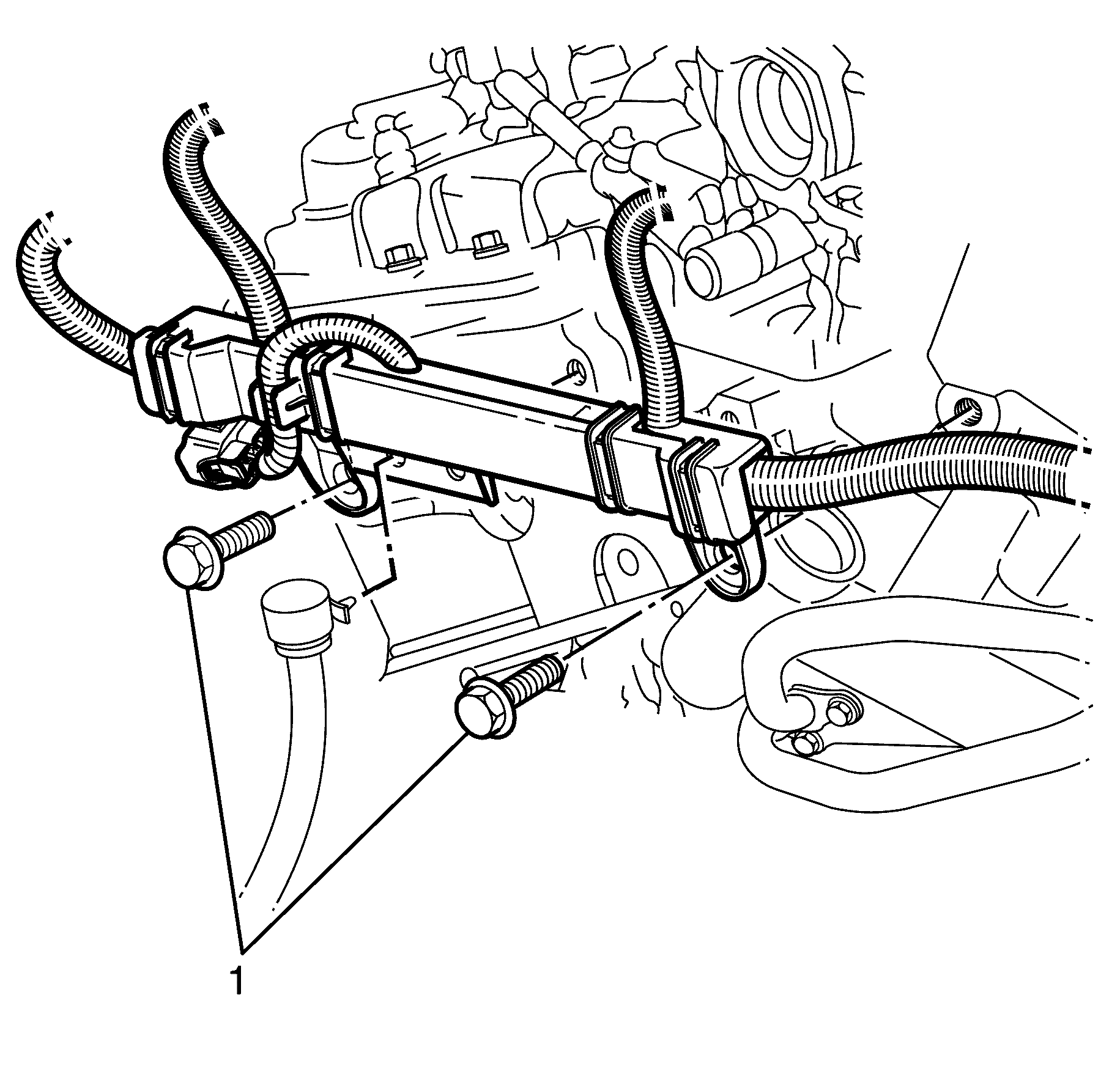
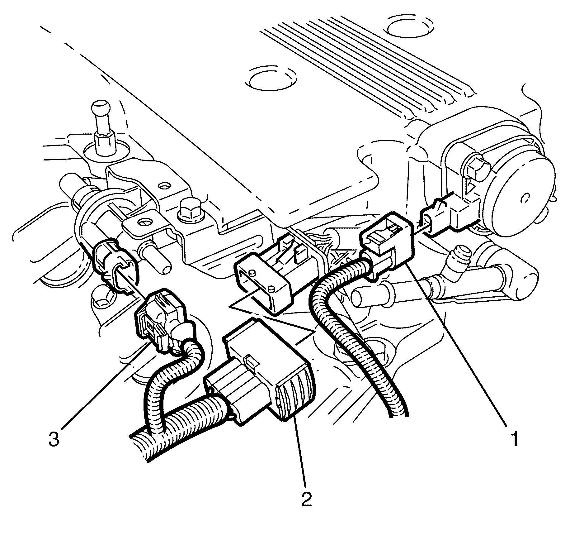
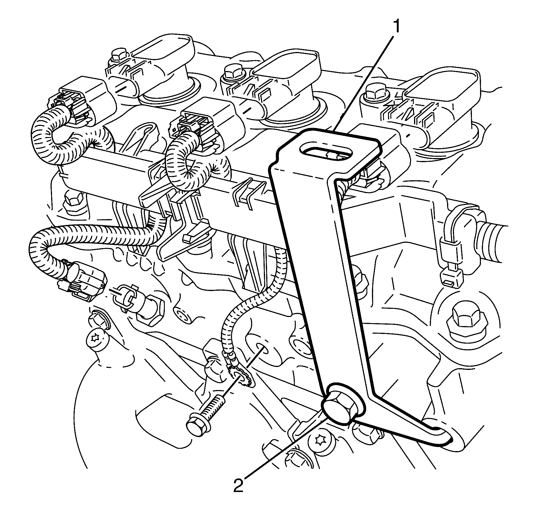
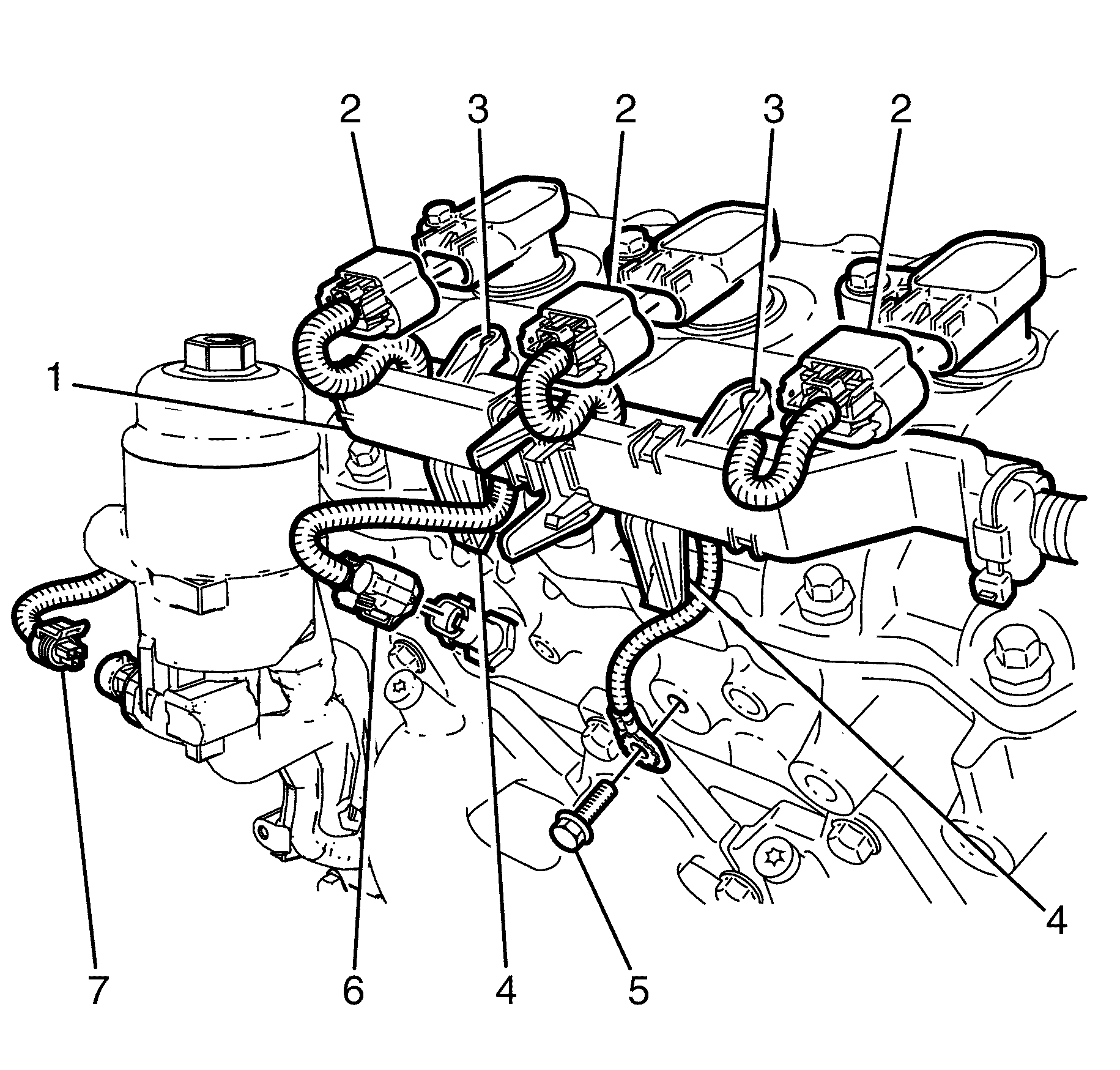
Important: Use a suitable tool to detach the engine wiring harness (1) clips from the right bank camshaft cover clips (4) then lift upwards to detach the engine wiring harness (1) from the right bank camshaft cover lugs (3).
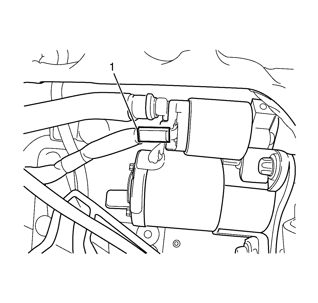
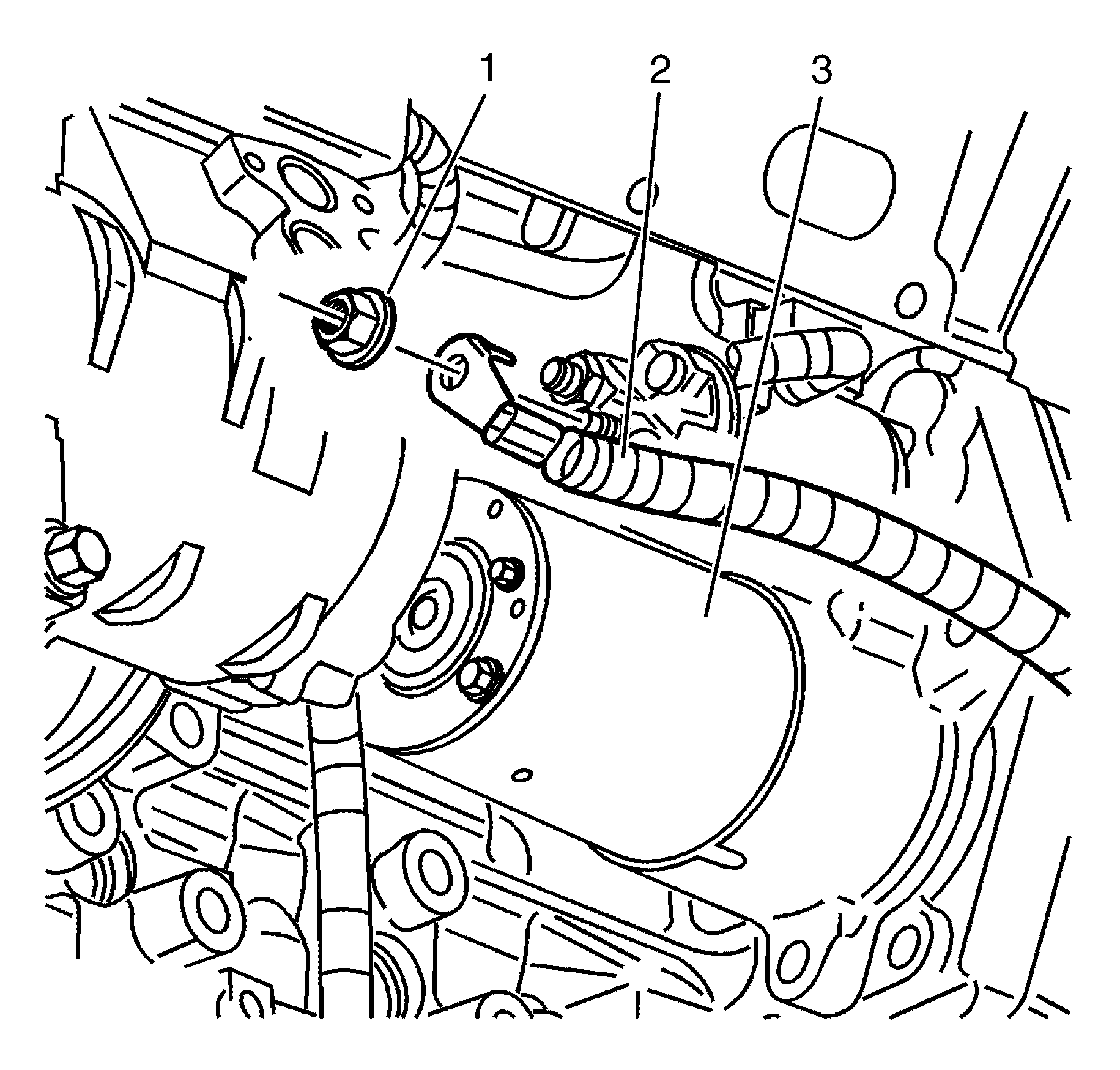
Important: DO NOT disconnect the power steering pipes or drain the power steering fluid.
Important: The locking tang on the power steering reservoir bracket (2) must be released before removing the power steering reservoir (1). Release the locking tang on the power steering reservoir bracket (2) with a suitable tool.
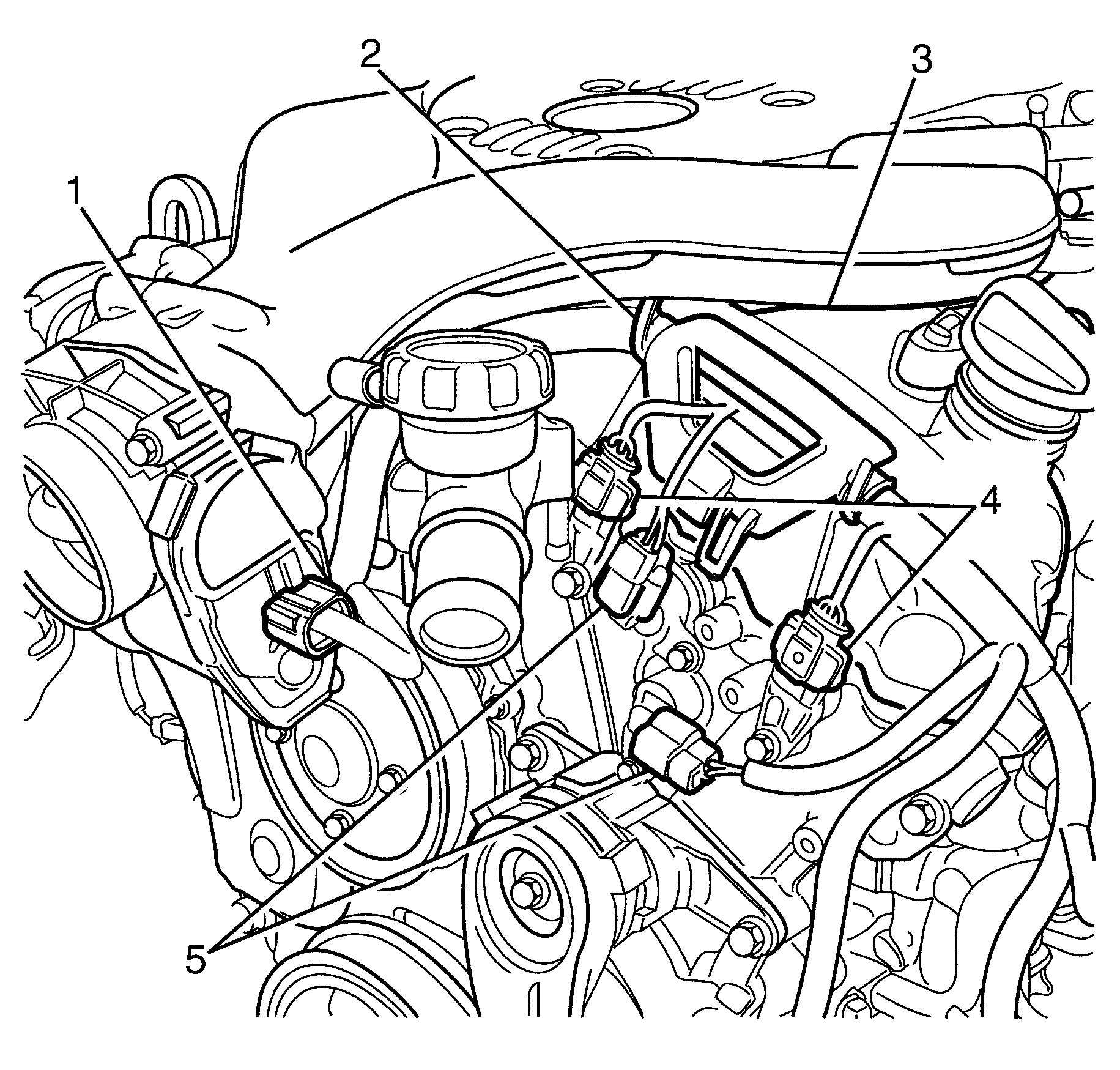
Important: LE0 and LW2 engines only have an intake camshaft position actuator valve.
Important: Use a suitable tool to detach the engine wiring harness bracket (2) from the locating clip lug on the left bank camshaft cover (3) then slide the engine wiring harness bracket (2) upwards to detach from the left bank camshaft cover (3).
