GM Service Manual Online
For 1990-2009 cars only

System Overview

The fuel tank stores the fuel supply. An electric fuel pump, located in the fuel tank with the fuel sender assembly that pumps the fuel to the fuel rail assembly. The pump provides the fuel at a pressure greater than is needed by the injectors. The fuel pressure regulator, part of the fuel sender assembly, keeps the fuel available to the injectors at a regulated pressure. The fuel system is returnless.

Fuel Tank

The fuel storage tank is made of high density polyethylene. The fuel storage tank is held in place by 2 metal straps that are attached to the under body of the vehicle. The tank shape includes a sump in order to maintain a constant supply of fuel around the fuel pump strainer during low fuel conditions or during aggressive manoeuvres.

The fuel tank also contains a fuel vapor vent valve with a roll-over protection. The vent valve also features a 2-phase vent calibration which increases the fuel vapor flow to the canister when the operating temperatures increase the tank pressure beyond an established threshold.

Fuel Tank Filler Pipe

In order to prevent refuelling with leaded fuel, the fuel filler pipe has a built-in restrictor and a deflector. The opening in the restrictor will accept only the smaller unleaded gasoline fuel nozzle which must be fully inserted in order to bypass the deflector. The tank is vented during filling by an internal vent tube inside of the filler pipe.

Fuel Filler Cap


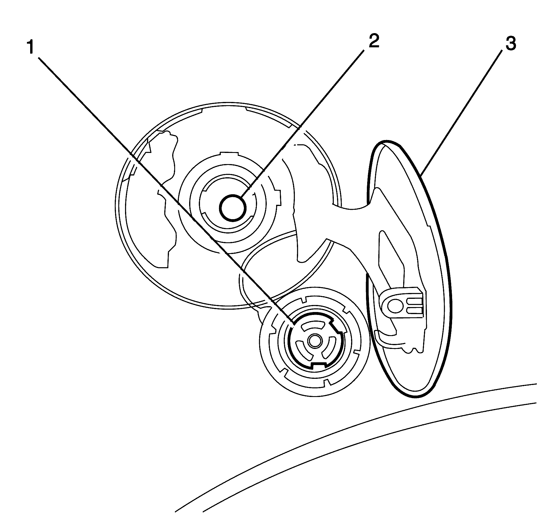
Object Number: 1962295  Size: SH
(1)Fuel Tank Filler Cap
(2)Fuel Tank Filler Pipe
(3)Fuel Filler Door

Notice: If a fuel tank filler cap requires replacement, use only a fuel tank filler cap with the same features. Failure to use the correct fuel tank filler cap can result in a serious malfunction of the fuel and EVAP system.

The fuel filler cap (1) is a screw-on type, with an integrated tightening torque limiting mechanism. When installing the cap, tighten it until a ratcheting (clicking) sound is heard, indicating the cap is properly tightened. The fuel tank filler cap is tethered to the fuel filler pocket. The fuel tank filler cap requires a quarter of a turn in order to be removed.
Modular Fuel Sender


Object Number: 1962296  Size: SH
(1)Secondary Fuel Level Sensor - Left
(2)Fuel feed line to Engine
(3)2-Way Check Valve - Fuel Supply
(4)Siphon Jet Pump
(5)Primary Fuel Level Sensor - Right
(6)Fuel Reservoir/Bucket
(7)Fuel Pump
(8)Fuel Strainer/Pick up
(9)Return Fuel Check Valve for Reservoir
(10)Return Fuel Jet Pump
(11)Fuel Transfer Line
(12)Fuel Strainer/Pickup

The modular fuel sender assembly mounts to the threaded opening of the plastic fuel tank with a seal and a retainer ring. The reservoir, containing the exterior inlet strainer, the electric fuel pump and the pump strainer, maintains contact with the tank bottom. This design provides:

    • Optimum fuel level in the integral fuel reservoir during all fuel tank levels and during driving conditions
    • An improved tank fuel level measuring accuracy
    • An improved coarse straining and added pump inlet filtering
    • More extensive internal fuel pump isolation for noiseless operation

The modular fuel sender assembly maintains an optimum fuel level in the reservoir (bucket). The fuel entering the reservoir is drawn in by the following components:

    • The first stage of the fuel pump through the external strainer
        and/or
    • The secondary umbrella valve
        or
    • The return fuel line, whenever the level of fuel is below the top of the reservoir

Fuel Pump


Object Number: 1965569  Size: MF

The fuel pump is incorporated into the design of the modular fuel sender assembly inside the fuel tank and is an electric, high pressure, single turbine design. The fuel pump provides fuel to the fuel rail assembly at a specified flow and pressure. The fuel pump delivers a constant flow of fuel to the engine, even during low fuel conditions or aggressive vehicle manoeuvres. The engine control module (ECM) controls the electric fuel pump operation through the fuel pump relay.

Fuel Pressure Regulator Assembly

The fuel pressure regulator is a diaphragm-operated relief valve located in the modular fuel pump and sender assembly. Its principal function is to maintain a controlled pressure at the injectors at all times by regulating fuel flow into the fuel feed line. With the ignition ON and the engine OFF, system fuel pressure at the pressure test connection should be 380-440 kPa (55-64 psi).

Fuel Pump Strainer

The fuel strainer connects onto the fuel pump inlet port on the end cap of the fuel pump assembly and consists of a finely woven plastic filter. A metal compression ring is fitted around the plastic strainer to fuel pump feed port and the complete fuel strainer assembly is fastened to the fuel pump end cap with a metal speed clip fastener. The strainers function is to filter fuel contaminants from within the fuel reservoir and also act to wick the fuel. The fuel strainer is serviced as part of the complete fuel pump and strainer assembly. Fuel stoppage at the strainer indicates an abnormal amount of sediment in the fuel tank which should be removed before reinstallation of the fuel tank into the vehicle.

Fuel Filter Assembly

The fuel filter assembly is contained within the modular fuel pump and sender assembly reservoir and forms the containment housing for the fuel pump. The filter comprises a paper element which traps particles in the fuel that may damage the fuel injection system. The fuel filter is made to withstand maximum fuel system pressure, changes in temperature and exposure to fuel additives.

Fuel Level Sender Assemblies

The fuel level sender assembly comprises of two fuel level float and wire arm assemblies, a ceramic variable resistor card assembly , and a detachable nylon wiper. The ceramic resistor card is attached to a plastic card holder which attaches to the reservoir. A metal contact fork with brushes is connected to the detachable nylon wiper. This assembly provides a variable circuit resistance to the engine control module (ECM) depending on wiper contact position. Two circuit wires run from the resistor card and extend up to connect with the modular fuel pump to cover assembly wiring connector on the underside of the modular fuel pump and sender assembly cover. The ECM averages out any slosh variation in the fuel tank and sends this signal to the fuel level indicator on the instrument panel fuel gauge.

Nylon Fuel Pipes

Caution: In order to reduce the risk of fire and personal injury observe the following items:

   • Replace all nylon fuel pipes that are nicked, scratched or damaged during installation, do not attempt to repair the sections of the nylon fuel pipes
   • Do not hammer directly on the fuel harness body clips when installing new fuel pipes. Damage to the nylon pipes may result in a fuel leak.
   • Always cover nylon vapor pipes with a wet towel before using a torch near them. Also, never expose the vehicle to temperatures higher than 115°C (239°F) for more than one hour, or more than 90°C (194°F) for any extended period.
   • Apply a few drops of clean engine oil to the male pipe ends before connecting fuel pipe fittings. This will ensure proper reconnection and prevent a possible fuel leak. (During normal operation, the O-rings located in the female connector will swell and may prevent proper reconnection if not lubricated.)

Important:  The fuel pipe "O" rings are not a serviceable item

Nylon fuel pipes are designed to perform the same job as the steel or flexible fuel pipes or hoses. Nylon pipes are constructed to withstand maximum fuel system pressure, exposure to fuel additives, and changes in temperature. There are three sizes of nylon pipes used: 3/8 in ID for the fuel feed, 5/16 in ID for the evaporative emission tube, and 1/2 in ID for the vent. Heat-resistant rubber hose and/or corrugated plastic conduit protect the sections of the pipes that are exposed to chafing, to high temperature or to vibration.

Nylon fuel pipes are somewhat flexible and can be formed around gradual turns under the vehicle. However, if nylon fuel pipes are forced into sharp bends, the pipes will kink and restrict the fuel flow. Once exposed to fuel, nylon pipes may become stiffer and are more likely to kink if the pipes are bent too far. Take special care when working on a vehicle with nylon fuel pipes.

Quick-Connect Fittings

Quick-connect fittings provide a simplified means of installing and connecting fuel system components. The fittings consist of a unique female connector and a compatible male pipe end. "O" rings, located inside the female connector, provide the fuel seal. Integral locking tabs or fingers hold the fittings together.

Fuel Pipe O-Rings

"O" rings seal the threaded connections in the fuel system. The fuel system "O" ring seals are made of a special material. The fuel pipe "O" rings are not a serviceable item.

EVAP Pipes and Hoses

The evaporative emission (EVAP) tubes extend from the fuel tank module and the EVAP canister vent to the EVAP canister. These tubes are located on the top rear of the fuel tank. The EVAP purge tube/pipe extends from the EVAP canister on top of the fuel tank to the EVAP purge solenoid in the engine compartment. The chassis EVAP purge pipe is constructed of steel.

On-Board Refueling Vapor Recovery System (ORVR)

The on-board refuelling vapour recovery system (ORVR) is an on-board vehicle system that is designed to recover the fuel vapours during the vehicle refuelling operation. The flow of liquid fuel down the fuel filler pipe provides a liquid seal, which prevents the vapour from leaving the fuel filler pipe. An evaporative emission (EVAP) pipe transports the fuel vapour to the EVAP canister for use by the engine. Listed below are the ORVR system components with a brief description of their operation:

    • The EVAP canister. The EVAP canister receives refuelling vapour from the fuel system, stores the vapour and releases the vapour to the engine upon demand.
    • The EVAP pipes. The EVAP pipes transport the fuel vapour from the fuel tank to the EVAP canister.
    • The fuel filler pipe. The fuel filler pipe carries the fuel from the fuel nozzle to the fuel tank.
    • The check valve. The check valve limits fuel spit back from the fuel tank during the refuelling operation by allowing the fuel flow only into the fuel tank. This check valve is located at the bottom of the fuel filler pipe.
    • The modular fuel sender assembly. The assembly pumps the fuel to the engine from the fuel tank.
    • The fill limiter vent valve (FLVV). This valve acts as a shut-off valve. The FLVV is located at the top of the fuel sender assembly. This valve is not serviced separately. The FLVV has the following functions:
       - The FLW controls the fuel tank fill level by closing the primary vent from the fuel tank.
       - The FLW prevents the fuel from exiting the fuel tank via the EVAP pipe to the canister.
       - The FLW provides fuel-spillage protection in the event of a vehicle roll over by closing the vapour path from the tank to the EVAP canister.

Modes of Operation

The engine control module (ECM) looks at voltages from several sensors to determine how much fuel to give the engine. The fuel is delivered under one of several conditions called modes. The ECM controls all modes.

Starting Mode

With the ignition ON, before engaging the starter, the engine control module (ECM) energizes the fuel pump relay for two seconds allowing the fuel pump to build up pressure. The ECM first checks speed density, then switches to the mass air flow (MAF) sensor. The ECM also uses the engine coolant temperature (ECT), throttle position (TP), and manifold absolute pressure (MAP) sensors to determine the proper air/fuel ratio for starting. The ECM controls the amount of fuel delivered in the starting mode by changing the pulse width of the injectors. This is done by pulsing the injectors for very short times.

Clear Flood Mode

If the engine is flooded with fuel during starting and will not start, the Clear Flood Mode can be manually selected. To select Clear Flood Mode, push the accelerator to wide open throttle (WOT). With this signal, the ECM will completely turn OFF the injectors and will maintain this stage as long as the ECM indicates a WOT condition with engine speed below 1,000 RPM.

Run Mode

The Run Mode has 2 conditions: Open Loop operation and Closed Loop operation. When the engine is first started and the engine speed is above 480 RPM, the system goes into Open Loop operation. In Open Loop operation, the ECM ignores the signals from the oxygen sensors and calculates the required injector pulse width based primarily on inputs from the MAF, IAT and ECT sensors.

In Closed Loop, the ECM adjusts the calculated injector pulse width for each bank of injectors based on the signals from each oxygen sensor.

Acceleration Mode

The ECM monitors the changes in the TP and the MAF sensor signals in order to determine when the vehicle is being accelerated. The ECM will then increase the injector pulse width in order to provide more fuel for improved performance.

Deceleration Mode

The ECM monitors changes in TP and MAF sensor signals to determine when the vehicle is being decelerated. The ECM will then decrease injector pulse width or even shut OFF injectors for short periods to reduce exhaust emissions, and for better (engine braking) deceleration.

Battery Voltage Correction Mode

The ECM can compensate in order to maintain acceptable vehicle driveability when the ECM sees a low battery voltage condition. The ECM compensates by performing the following functions:

    • Increasing the injector pulse width in order to maintain the proper amount of fuel being delivered
    • Increasing the idle speed to increase the generator output

Fuel Cutoff Mode

The engine control module (ECM) cuts OFF fuel from the fuel injectors when the following conditions are met in order to protect the powertrain from damage and improve driveability:

    • The ignition is OFF. This prevents engine run-on.
    • The ignition is ON, but there is no ignition reference signal. This prevents flooding or backfiring.
    • The engine speed is too high, above the red line.
    • The vehicle speed is too high, above rated tire speed.
    • During an extended, high speed, closed throttle coast down, this reduces emissions and increases engine braking.
    • During extended deceleration, in order to prevent damage to the catalytic converters.
    • The torque management enabled--Transmission shifts or abusive maneuvers.
    • The traction control enabled--In conjunction with the front brakes applying

Fuel Trim

The engine control module (ECM) controls the air/fuel metering system in order to provide the best possible combination of driveability, fuel economy and emission control. The ECM monitors the heated oxygen sensor (HO2S) signal voltage while in Closed Loop and regulates the fuel delivery by adjusting the pulse width of the fuel injectors based on this signal. The ideal fuel trim values are around 0 percent for both short term and long term fuel trim. A positive fuel trim value indicates the ECM is adding fuel in order to compensate for a lean condition by increasing the pulse width. A negative fuel trim value indicates that the ECM is reducing the amount of fuel in order to compensate for a rich condition by decreasing the pulse width. A change made to the fuel delivery changes the short term and long term fuel trim values. The short term fuel trim values change rapidly in response to the HO2S signal voltage. These changes fine tune the engine fuelling. The long term fuel trim makes coarse adjustments to the fuelling in order to re-centre and restore control to short term fuel trim. A scan tool can be used to monitor the short term and long term fuel trim values. The long term fuel trim diagnostic is based on an average of several of the long term speed load learn cells. The ECM selects the cells based on the engine speed and engine load. If the ECM detects an excessive lean or rich condition, the ECM will set a fuel trim DTC.

Fuel Pump Electrical Circuit

When the ignition switch is in the ON position, before engaging the starter, the engine control module (ECM) energizes the fuel pump relay for two seconds, causing the fuel pump to pressurize the fuel system. If the ECM does not receive ignition reference pulses with the engine cranking or running within two seconds, the ECM shuts OFF the fuel pump relay, causing the fuel pump to stop.

Fuel Rail Assembly


Object Number: 1965570  Size: MF

The fuel rail assembly attaches to the engine intake manifold. The fuel rail assembly performs the following functions:

    • Positions the injectors (3) in the intake manifold
    • Distributes fuel evenly to the injectors through the fuel rail (2)
    • Fuel Rail Feed Pipe (1)

Fuel Injectors

The top-feed fuel injector assembly is a solenoid-operated device, controlled by the engine control module (ECM), that meters pressurized fuel to a single engine cylinder. The ECM energizes the injector solenoid, which opens a ball valve, allowing the fuel to flow past the ball valve, and through a recessed flow director plate. The director plate has multiple machined holes that control the fuel flow, generating a conical spray pattern of finely atomized fuel at the injector tip. Fuel is directed at the intake valve, causing the fuel to become further atomized and vaporized before entering the combustion chamber. An injector that is stuck partly open can cause a loss of pressure after the engine shutdown. Consequently, long cranking times would be noticed on some engines.

Engine Fueling

The engine is fueled by eight individual injectors, one for each cylinder, that are controlled by the ECM. The ECM controls each injector by energizing the injector coil for a brief period once every other engine revolution. The length of this brief period, or pulse, is carefully calculated by the ECM to deliver the correct amount of fuel for proper driveability and emissions control. The period of time when the injector is energized is called the pulse width and is measured in milliseconds, thousandths of a second.

While the engine is running, the ECM is constantly monitoring the inputs and recalculating the appropriate pulse width for each injector. The pulse width calculation is based on the injector flow rate, mass of fuel the energized injector will pass per unit of time, the desired air/fuel ratio, and actual air mass in each cylinder and is adjusted for battery voltage, short term, and long term fuel trim. The calculated pulse is timed to occur as each cylinders intake valves are closing to attain largest duration and most vaporization.

Fueling during a crank is slightly different than fueling during an engine run. As the engine begins to turn, a prime pulse may be injected to speed starting. As soon as the ECM can determine where in the firing order the engine is, the ECM begins pulsing the injectors. The pulse width during the crank is based on the coolant temperature and the engine load.

The fueling system has several automatic adjustments in order to compensate for the differences in the fuel system hardware, the driving conditions, the fuel used, and the vehicle aging. The basis for the fuel control is the pulse width calculation that is described above. Included in this calculation are an adjustment for the battery voltage, the short term fuel trim, and the long term fuel trim. The battery voltage adjustment is necessary since the changes in the voltage across the injector affect the injector flow rate. The short term and the long term fuel trims are fine and gross adjustments to the pulse width that are designed in order to maximize the driveability and emissions control. These fuel trims are based on the feedback from the oxygen sensors in the exhaust stream and are only used when the fuel control system is in a Closed Loop operation.

Under certain conditions, the fueling system will turn OFF the injectors for a period of time. This is referred to as fuel shut-off. Fuel shut-off is used in order to improve traction, save fuel, improve emissions, and protect the vehicle under certain extreme or abusive conditions.

In case of a major internal problem, the ECM may be able to use a back-up fuel strategy for limp in mode that will run the engine until service can be performed.

Sequential Fuel Injection (SFI)

The ECM controls the fuel injectors based on information that the ECM receives from several information sensors. Each injector is fired individually in the engine firing order, which is called sequential fuel injection. This allows precise fuel metering to each cylinder and improves the driveability under all of the driving conditions.

The ECM has several operating modes for fuel control, depending on the information that has been received from the sensors.