Heated Oxygen Sensor Replacement - Bank 1 Sensor 1 NT3
Removal Procedure
- Ignition OFF.
- Raise and support the vehicle. Refer to Lifting and Jacking the Vehicle.
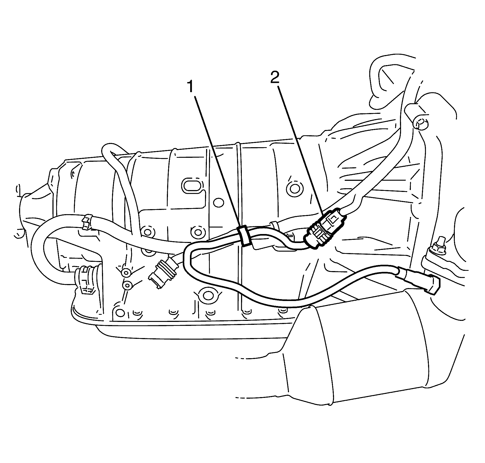
- Disconnect the heated oxygen sensor (HO2S) from the electrical connector retaining clip (1).
- Disconnect the heated oxygen sensor (HO2S) electrical connector (2) from the harness connector on the transmission case.
- Remove the catalytic converter. refer to Catalytic Converter Replacement - Right Side.
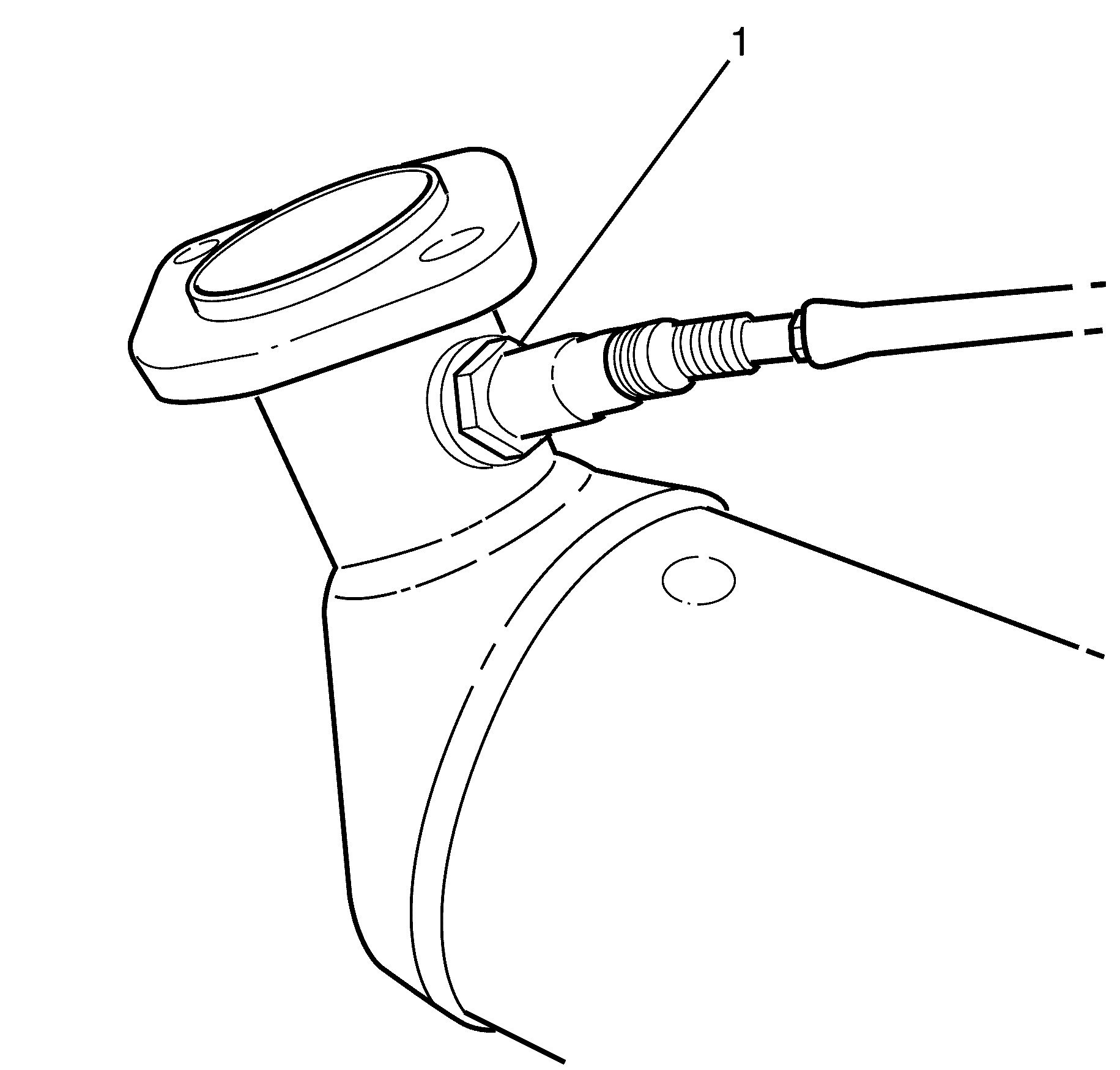
- Remove the HO2S (1) from the catalytic converter.
Caution: Refer to Safety Glasses Caution in the Preface section.
Caution: Refer to Vehicle Lifting Caution in the Preface section.

Notice: Refer to Heated Oxygen and Oxygen Sensor Notice in the Preface section.

Installation Procedure
- Install the HO2S to the catalytic converter.
- Install the catalytic converter to the vehicle. Refer to Catalytic Converter Replacement - Right Side.
- Connect the heated oxygen sensor (HO2S) electrical connector (2) to the harness connector on the transmission case.
- Connect the heated oxygen sensor (HO2S) to the electrical connector retaining clip (1).
- Lower the vehicle.
Notice: Refer to Component Fastener Tightening Notice in the Preface section.

Important: New oxygen sensors should have a special anti-seize compound already applied to the sensor threads. If you are installing the original sensor, apply an approved anti-seize compound to the sensor threads.
Tighten
Tighten the HO2S to 40 N·m (30 lb ft).

Heated Oxygen Sensor Replacement - Bank 1 Sensor 1 NT4
Removal Procedure
- Ignition OFF.
- Disconnect the negative battery cable. Refer to Battery Negative Cable Disconnection and Connection .
- Remove the engine cover. Refer to Engine Cover Replacement .
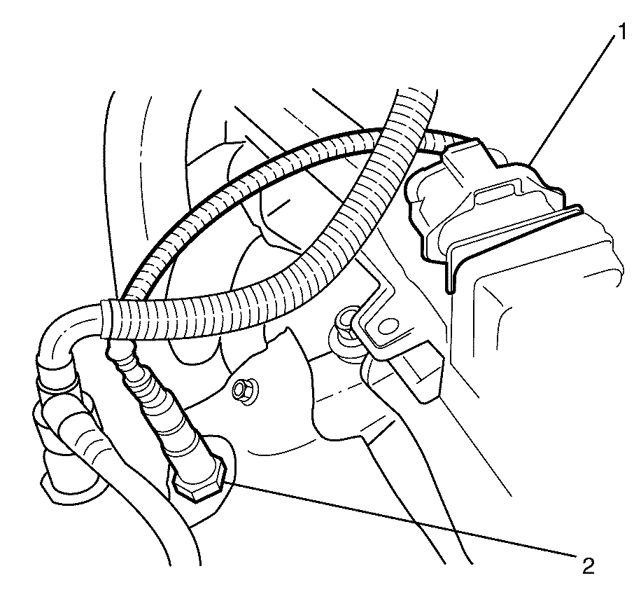
- Disconnect the heated oxygen sensor (HO2S) electrical connector (1).
- Remove the HO2S (2) from the exhaust manifold.
Caution: Refer to Battery Disconnect Warning in the Preface section.

Notice: Refer to Heated Oxygen and Oxygen Sensor Notice in the Preface section.
Installation Procedure
- Install the HO2S (2) into the exhaust manifold.
- Connect the HO2S electrical connector (1).
- Install the engine cover. Refer to Engine Cover Replacement.
- Connect the negative battery cable. Refer to Battery Negative Cable Disconnection and Connection .
Notice: Refer to Component Fastener Tightening Notice in the Preface section.

Important: New oxygen sensors should have a special anti-seize compound already applied to the sensor threads. If you are installing the original sensor, apply an approved anti-seize compound to the sensor threads.
Tighten
Tighten the HO2S to 40 N·m (30 lb ft).
