- Remove the hood. Refer to
Hood Replacement
in Body Front End.
- Remove the battery. Refer to
Battery Replacement
in Engine Electrical.
- Remove the fuel injector sight shield. Refer to
Fuel Injector Sight Shield Replacement
.
- Disconnect the vacuum brake booster hose from the vacuum connections
and position aside.
- Disconnect the fuel feed and return lines from the fuel rail and
secure to the air inlet grill. Refer to
Metal Collar Quick Connect Fitting Service
or
Plastic Collar Quick Connect Fitting Service
in Engine Controls-3.8L.
- Remove the evaporative emission canister purge valve and secure
the hose to the air inlet grill. Refer to
Evaporative Emission Canister Purge Solenoid Valve Replacement
in Engine Controls-3.8 L.
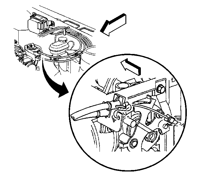
- Push the lock release
and remove the cruise control cable from the throttle body bracket and lever.
- Disconnect the electrical connector from the cruise control module.
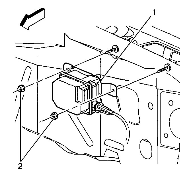
- Remove the retaining nuts (2)
and the cruise control module (1) from the mounting studs.
Caution: In order to avoid possible injury or vehicle damage, always replace
the accelerator control cable with a NEW cable whenever you remove the engine
from the vehicle.
In order to avoid cruise control cable damage, position the cable out
of the way while you remove or install the engine. Do not pry
or lean against the cruise control cable and do not kink the cable. You must
replace a damaged cable.
- Remove the accelerator control cable. Refer to
Cruise Control Cable Replacement
in Cruise Control.
- Remove the drive belt. Refer to
Drive Belt Replacement
.
- Raise and support the vehicle. Refer to
Lifting and Jacking the Vehicle
in General Information.
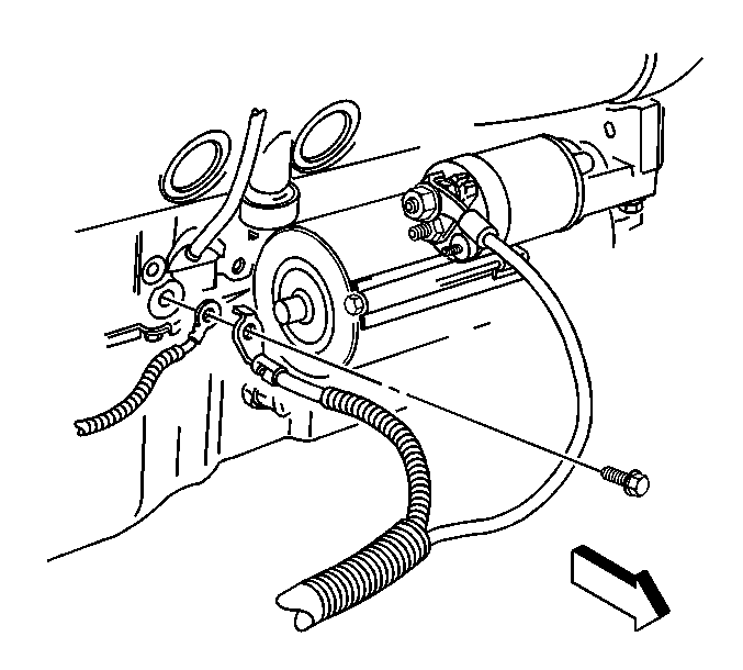
- Remove the bolt securing
both the battery negative cable and the engine harness ground lead to the
engine block.
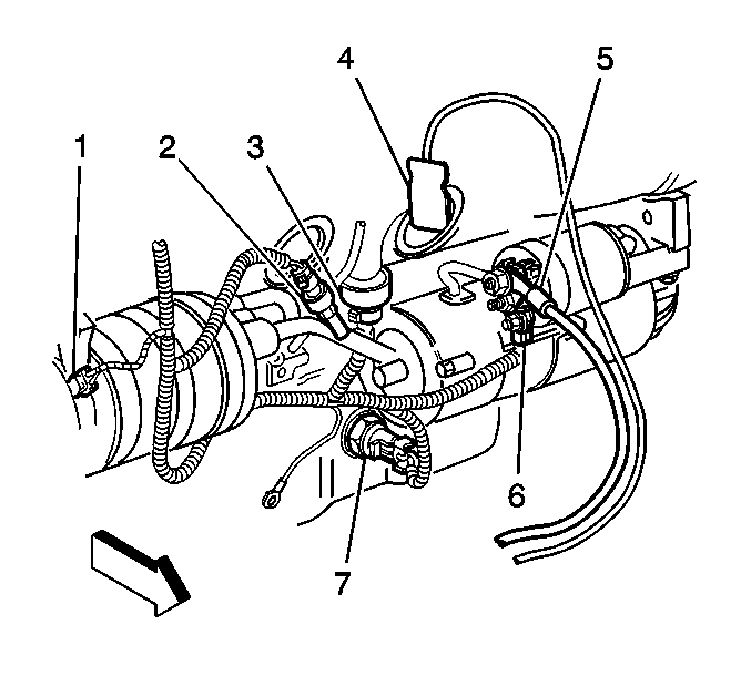
- Disconnect the wiring
harness connectors from the following components:
| • | The A/C compressor clutch (1) |
| • | The A/C pressure sensor (2) |
| • | The knock sensor #1 (3) |
| • | The engine coolant block heater (4) |
| • | The oil level sensor (7) |
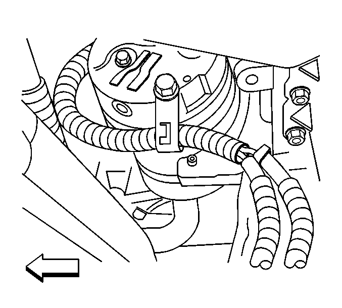
- Disconnect the wiring
harness from the harness clip at the rear of the A/C compressor.
- Remove the torque converter cover. Refer to
Torque Converter Cover Replacement
in Automatic Transaxle-4T65-E.
- Remove the starter motor. Refer to
Starter Motor Replacement
in Engine Electrical.
- Remove the bolts securing the flywheel to the torque converter.
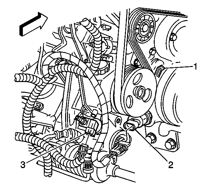
- Disconnect and secure
the following wiring harness electrical connectors to the cowl:
| • | The knock sensor #2, located behind the right exhaust manifold |
| • | The oil pressure sensor (2) |
| • | The vehicle speed sensor (VSS) (3) |
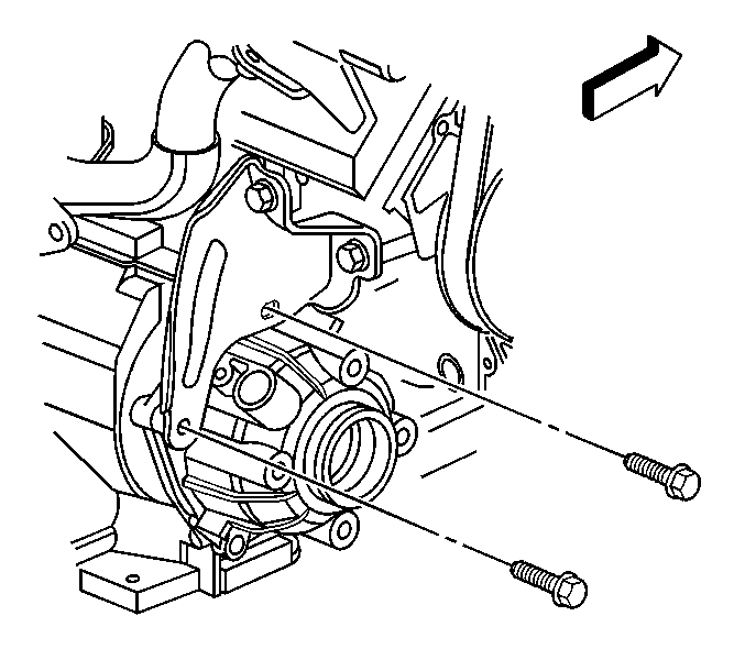
- Remove the 2 bolts securing
the transaxle brace to the transaxle.
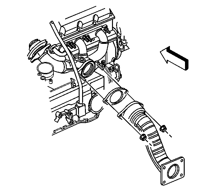
Caution: Always wear protective goggles and gloves when removing exhaust parts
as falling rust and sharp edges from worn exhaust components could result
in serious personal injury.
- Remove the 2 nuts attaching the exhaust manifold pipe
to the right exhaust manifold.
- Remove the exhaust manifold pipe from the right exhaust manifold
studs, allowing it to rest on top of the power steering gear heat shield.
Remove the gasket. Do not reuse the gasket.
- Remove the right front fascia extension. Refer to
Front Bumper Fascia Extension Replacement
in Bumpers.
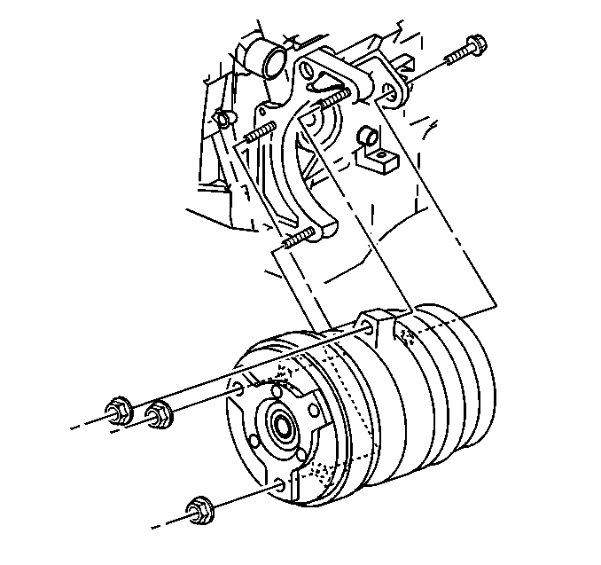
- Remove the front A/C compressor
mounting nuts.
- Remove the rear A/C compressor mounting bolt.
- Slide the A/C compressor forward off of the mounting studs and
allow the compressor to rest on top of the engine frame.
- Lower the vehicle.
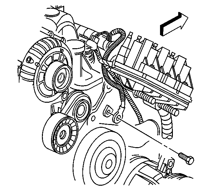
- Remove the bolt securing
the PCM ground located at the left front cylinder head.
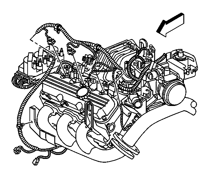
- Disconnect the wiring
harness electrical connectors from the following components on the left
side of the engine:
| • | The boost control solenoid (L67 only) |
| • | The engine coolant temperature (ECT) sensor |
| • | The throttle position (TP) sensor |
| • | The idle air control (IAC) valve |
| • | The mass air flow (MAF) sensor |
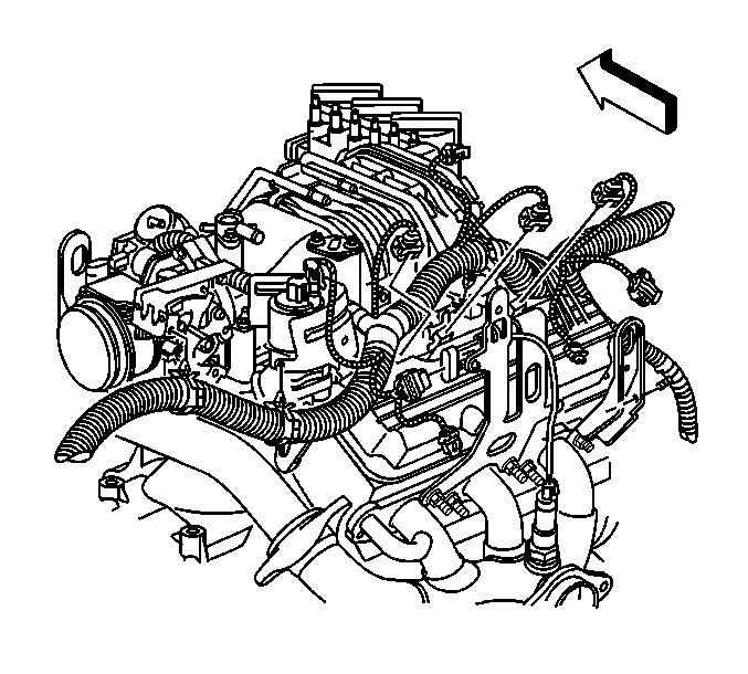
- Disconnect the wiring
harness connectors from the following components on the right side of the
engine:
| • | Exhaust gas recirculation (EGR) valve |
| • | Manifold absolute pressure (MAP) sensor |
| • | Heated oxygen sensor (HO2S) |
| • | AIR solenoid, if equipped with NC8 |
- Secure the engine wiring harness rearward to the air inlet grill.
- Remove the generator. Refer to
Generator Replacement
in Engine Electrical.
- Remove the air cleaner intake duct. Refer to
Air Cleaner Inlet Duct Replacement
in Engine Controls-3.8L.
- Install the engine support fixture. Refer to
Engine Support Fixture
.
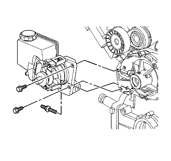
- Remove the two front power
steering pump mounting bolts.
- Raise and support the vehicle. Refer to
Lifting and Jacking the Vehicle
in General Information.
- Remove the side power steering pump mounting bolt.
- Position the power steering pump against the cowl, allowing it
to rest on top of the transaxle housing.
- Remove the right engine mount bracket. Refer to
Engine Mount Bracket Replacement - Right Side
.
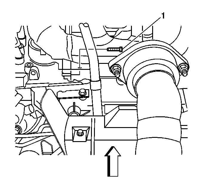
- Remove the right lower
engine to transaxle mounting bolt (1).
- Drain the cooling system. Refer to
Cooling System Draining and Filling
in Engine Cooling
- Lower the vehicle.
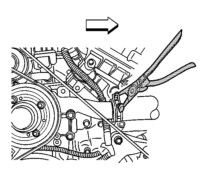
- Position the J 38185
to the clamp in order to remove the
radiator inlet hose from the water pump.
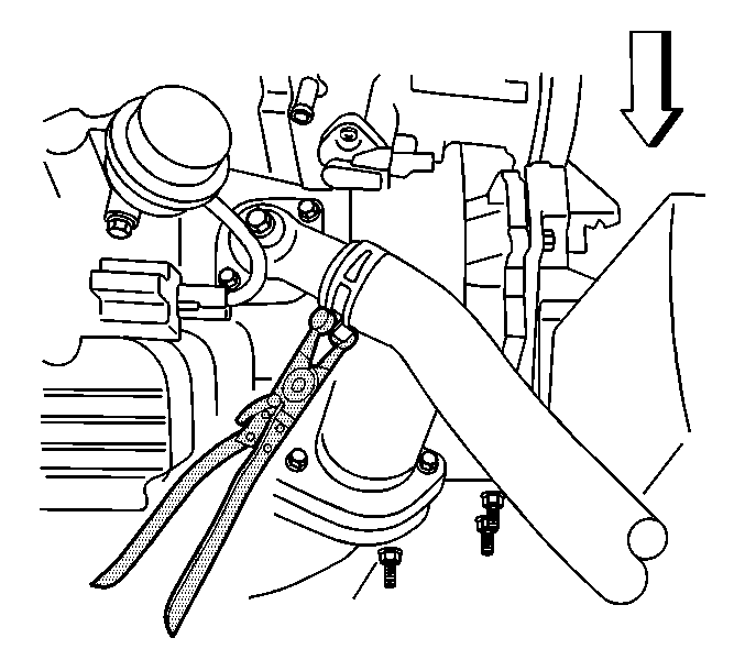
- Position the J 38185
to the clamp in order to remove the
radiator outlet hose from the thermostat housing.
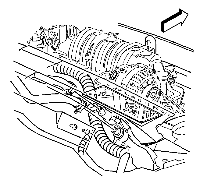
- Remove the heater hoses
from the drive belt tensioner fittings.
- Using a block of wood between a floor jack and the transaxle,
support the transaxle at the pan.
- Remove the engine support fixture. Refer to
Engine Support Fixture
.
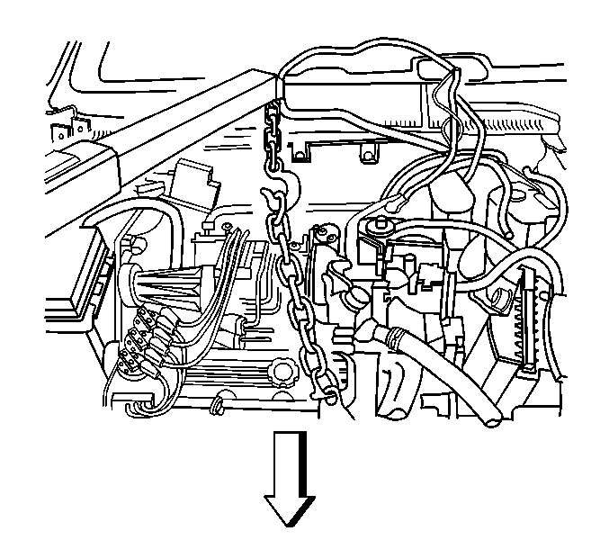
- Install a engine lift
chain to the engine lift brackets and attach to an engine lift devise.
- Remove the remaining engine to transaxle mounting bolts.
Important: Ensure clearance is maintained between the engine and the following:
| • | Engine wiring electrical harness |
- Carefully raise the engine from the engine compartment.
- Drain the engine oil. Refer to
Engine Oil and Oil Filter Replacement
.
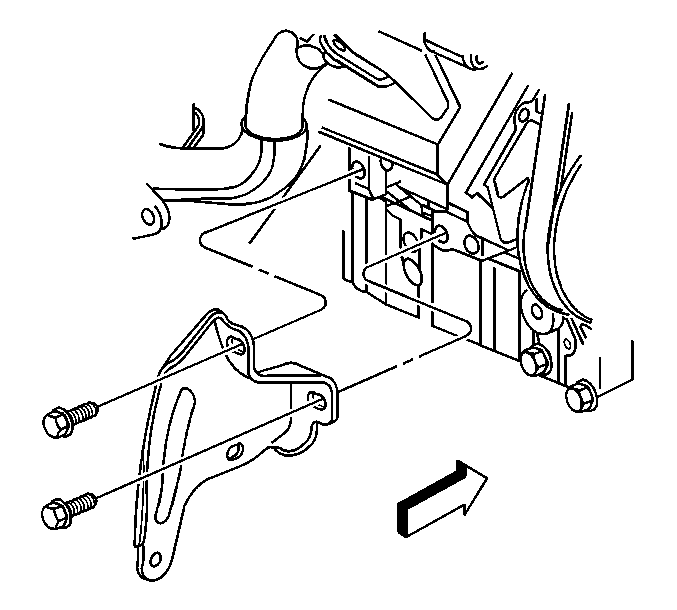
- Remove the 2 bolts securing
the transaxle brace to the engine.
- Remove the exhaust manifold pipe. Refer to
Exhaust Manifold Pipe Replacement
in Engine Exhaust.

- Loosely install the 2
bolts securing the transaxle brace to the engine. Do not tighten at this
time.
- Install the exhaust manifold pipe. Refer to
Exhaust Manifold Pipe Replacement
in Engine Exhaust.

Important: Ensure clearance is maintained between the engine and the following:
| • | The A/C accumulator hose |
| • | The A/C compressor hose |
| • | The engine wiring electrical harness |
| • | The vacuum brake booster |
- Carefully lower the engine into the engine compartment.
- Align the engine dowels to the transaxle cover.
Notice: Use the correct fastener in the correct location. Replacement fasteners
must be the correct part number for that application. Fasteners requiring
replacement or fasteners requiring the use of thread locking compound or sealant
are identified in the service procedure. Do not use paints, lubricants, or
corrosion inhibitors on fasteners or fastener joint surfaces unless specified.
These coatings affect fastener torque and joint clamping force and may damage
the fastener. Use the correct tightening sequence and specifications when
installing fasteners in order to avoid damage to parts and systems.
- Install the 5 upper engine to transaxle mounting bolts.
Tighten
Tighten the engine to transaxle mounting bolts to 75 N·m
(55 lb ft).
- Remove the engine lift chain from the engine lift brackets.
- Install the engine support fixture. Refer to
Engine Support Fixture
.
- Remove the support jack from under the transaxle.

- Connect the heater hoses
to the drive belt tensioner fittings.

- Position the J 38185
to the clamp in order to connect the
radiator outlet hose to the thermostat housing.

- Position the J 38185
to the clamp in order to connect the
radiator inlet hose to the water pump.
- Fill the cooling system. Refer to
Cooling System Draining and Filling
in Engine Cooling.
- Raise and support the vehicle. Refer to
Lifting and Jacking the Vehicle
in General Information.

- Install the right lower
engine to transaxle mounting bolt (1).
Tighten
Tighten the engine to transaxle mounting bolt to 75 N·m
(55 lb ft).
- Install the right engine mount bracket. Refer to
Engine Mount Bracket Replacement - Right Side
.

- Position the power steering
pump to the engine.
- Loosely install the side power steering pump mounting bolt. Do
not tighten at this time.
- Lower the vehicle.
- Install the 2 front power steering pump mounting bolts.
Tighten
Tighten the power steering pump mounting bolts to 27 N·m
(20 lb ft).
- Remove the engine support fixture. Refer to
Engine Support Fixture
.
- Install the air cleaner intake duct. Refer to
Air Cleaner Inlet Duct Replacement
in Engine Controls-3.8L.
- Install the generator. Refer to
Generator Replacement
in Engine Electrical.

- Position the engine wiring
electrical harness to the engine.
- Connect the wiring harness electrical connectors to the following
components on the right side of the engine:
| • | The exhaust gas recirculation (EGR) valve |
| • | The manifold absolute pressure (MAP) sensor |
| • | The heated oxygen sensor (HO2S) |
| • | The AIR solenoid, if equipped with NC8 |

- Connect the wiring harness
electrical connectors to the following components on the left side of the
engine:
| • | The boost control solenoid (L67 only) |
| • | The engine coolant temperature (ECT) sensor |
| • | The throttle position (TP) sensor |
| • | The idle air control (IAC) valve |
| • | The mass air flow (MAF) sensor |

- Install the bolt securing
the PCM ground to the left front cylinder head.
Tighten
Tighten the PCM ground lead bolt to 50 N·m (37 lb ft).
- Raise and support the vehicle. Refer to
Lifting and Jacking the Vehicle
in General Information.
- Tighten the side power steering pump mounting bolt previously
installed in step 14.
Tighten
Tighten the power steering pump mounting bolt to 27 N·m
(20 lb ft).

- Slide the A/C compressor
rearward over the mounting studs.
- Install the rear A/C compressor mounting bolt.
- Install the front A/C compressor mounting nuts.
Tighten
Tighten the A/C compressor mounting fasteners to 50 N·m
(37 lb ft).

- Place a NEW exhaust manifold
pipe gasket over the right exhaust manifold studs.
- Position the exhaust manifold pipe to the right exhaust manifold.
- Install the 2 nuts attaching the exhaust manifold pipe to the
right exhaust manifold.
Tighten
Tighten the exhaust manifold pipe nuts to 40 N·m (30 lb ft).

- Install the 2 bolts
securing the transaxle brace to the transaxle.
Tighten the 2 bolts
previously installed in step 1.
Tighten
Tighten the transaxle brace bolts to 65 N·m (48 lb ft).

- Connect the wiring harness
electrical connectors to the following components
| • | The knock sensor #2, located behind the right exhaust manifold |
| • | The oil pressure sensor (2) |
| • | The vehicle speed sensor (VSS) (3) |
- Install the bolts securing the flywheel to the torque converter.
Tighten
Tighten the flywheel to torque converter bolts to 63 N·m
(46 lb ft).
- Install the starter motor. Refer to
Starter Motor Replacement
in Engine Electrical.
- Install the torque converter cover. Refer to
Torque Converter Cover Replacement
in Automatic Transaxle-4T65-E.

- Connect the wiring harness
to the harness clip at the rear of the A/C compressor.

- Connect the wiring harness
connectors to the following components:
| • | A/C compressor clutch (1) |
| • | A/C pressure sensor (2) |
| • | Engine coolant block heater (4) |

- Install the bolt in order
to secure both the battery negative cable and the engine harness ground
lead to the engine block.
Tighten
Tighten the battery negative cable to engine block bolt to 25 N·m
(18 lb ft).
- Install the right front fascia extension. Refer to
Front Bumper Fascia Extension Replacement
in Bumpers.
- Lower the vehicle.
- Install the drive belt. Refer to
Drive Belt Replacement
.
Caution: In order to avoid possible injury or vehicle damage, always replace
the accelerator control cable with a NEW cable whenever you remove the engine
from the vehicle.
In order to avoid cruise control cable damage, position the cable out
of the way while you remove or install the engine. Do not pry
or lean against the cruise control cable and do not kink the cable. You must
replace a damaged cable.
- Remove the accelerator control cable. Refer to
Cruise Control Cable Replacement
in Cruise Control.

- Position the cruise control
module (1) to the mounting studs on the cowl.
Install
the 2 cruise control module bracket retaining nuts (2).
Tighten
Tighten the cruise control module bracket retaining nuts to 9 N·m
(80 lb ft).
- Connect the electrical connector to the cruise control module.

- Install the cruise control
cable to the throttle body lever.
- Slide the cruise control cable fully into the throttle body bracket
until it snaps into place.
- Install the evaporative emission canister purge valve. Refer to
Evaporative Emission Canister Purge Solenoid Valve Replacement
in Engine Controls-3.8L.
- Connect the fuel feed and return lines to the fuel rail. Refer
to
Metal Collar Quick Connect Fitting Service
or
Plastic Collar Quick Connect Fitting Service
in Engine Controls-3.8L.
- Connect the vacuum brake booster hose to the vacuum connections.
- Install the fuel injector sight shield. Refer to
Fuel Injector Sight Shield Replacement
.
- Install the battery. Refer to
Battery Replacement
in Engine Electrical.
- Install the hood. Refer to
Hood Replacement
in Body Front End.
- Fill the engine oil. Refer to
Engine Oil and Oil Filter Replacement
.


