Caution: Unless directed otherwise, the ignition and start switch must be in the OFF or LOCK position, and all electrical loads must be OFF before servicing
any electrical component. Disconnect the negative battery cable to prevent an electrical spark should a tool or equipment come in contact with an exposed electrical terminal. Failure to follow these precautions may result in personal injury and/or damage to
the vehicle or its components.
- Disconnect
the negative battery cable.
- Remove the wiper arms. Refer to
Windshield Wiper Arm Replacement
in Wipers Wash Systems.
- Remove the air inlet grilles. Refer to
Air Inlet Grille Panel Replacement
in Body Front End.
- Remove the hood. Refer to
Hood Replacement
in Body Front End.
- Remove the battery. Refer to
Battery Replacement
in Engine Electrical.
- Recover the refrigerant. Refer to Refrigerant Recovery and Recharging
in HVAC with Automatic A/C.
- Drain the coolant. Refer to
Cooling System Draining and Filling
in Engine Cooling.
- Remove the intake air resonator. Refer to
Intake Air Resonator Replacement
in Engine Controls.
- Release the air filter housing from the rubber grommets and remove
the air filter housing.
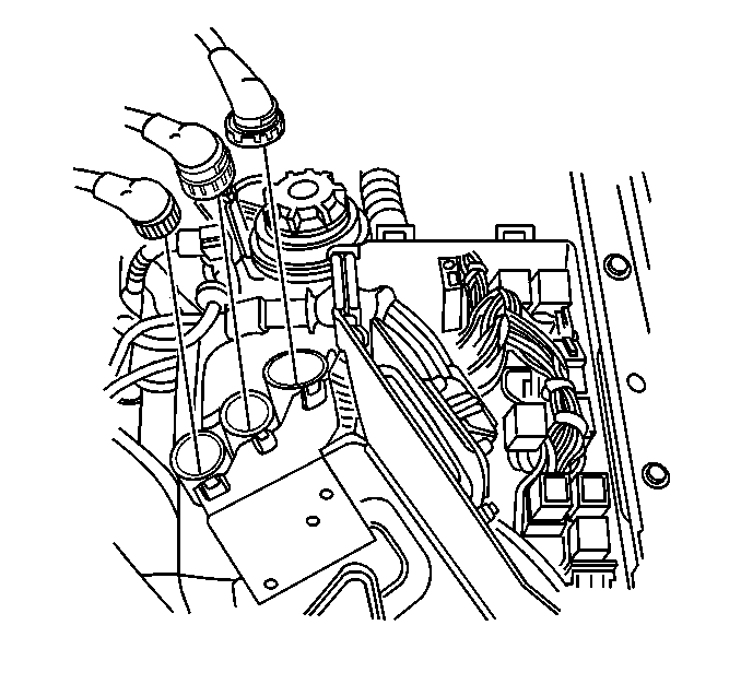
Important: Tag all of the wires removed to prevent improper reinstallation.
- Disconnect the large wiring harness connectors (1).
- Remove the body ground wire from the negative battery cable end.
- Remove the four power supply wires from the battery positive cable
end.
- Siphon the power steering fluid from the power steering reservoir.
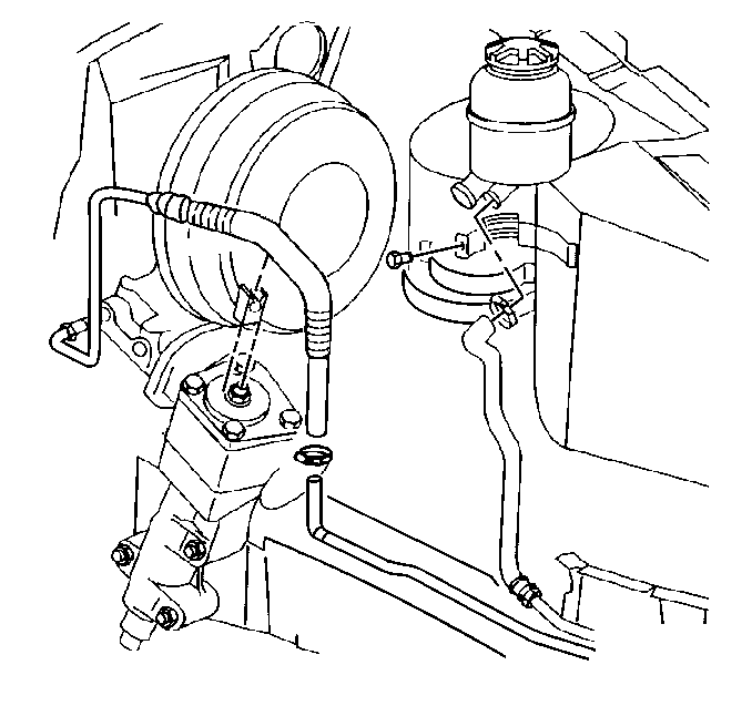
- Release the power steering
suction hose clamp and remove the power steering suction hose from the reservoir.
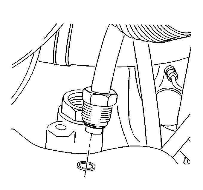
- Remove the power steering
discharge hose fitting (a crow's foot wrench works best) from the power steering
pump.
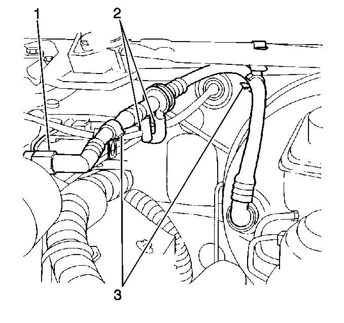
Important: Tag all of the vacuum hoses to aid in reassembly.
- Remove the brake booster threaded vacuum fitting from the intake plenum
(1).
- Remove the vacuum hoses (2) from the brake power booster hose.

- Unclip the ECM from the
underhood electrical center.
- Unclip the relays from the electrical center box to enable removal
of the entire wiring harness (ECM included) from the electrical center.
- Drape the entire wiring harness over the top of the engine and
secure to prevent interference when removing the engine.
- Relieve the fuel system pressure.
Important: Counterhold the fuel supply and return hose connections to prevent damage
to the fuel rail.
Residual fuel may be present in the supply hose, provide a means to
capture fuel if necessary.
- Disconnect the fuel supply and return hose connections.
- Release the throttle body coolant hose clamp and remove the hose
from the throttle body.
- Remove the vacuum hose from the purge valve located on top of
the engine ventilation chamber. (The engine ventilation chamber is located
on the rear, passenger side of the engine.)

- Remove the vacuum hose
from the hot water control valve.
- Release the coolant reservoir hose clamp and remove the hose from
the coolant intake pipe.
- Remove the electric heater water pump screws from the RH side
of the engine compartment.
- Drape the electric heater water pump (with hoses still attached)
over the top of the engine and secure.
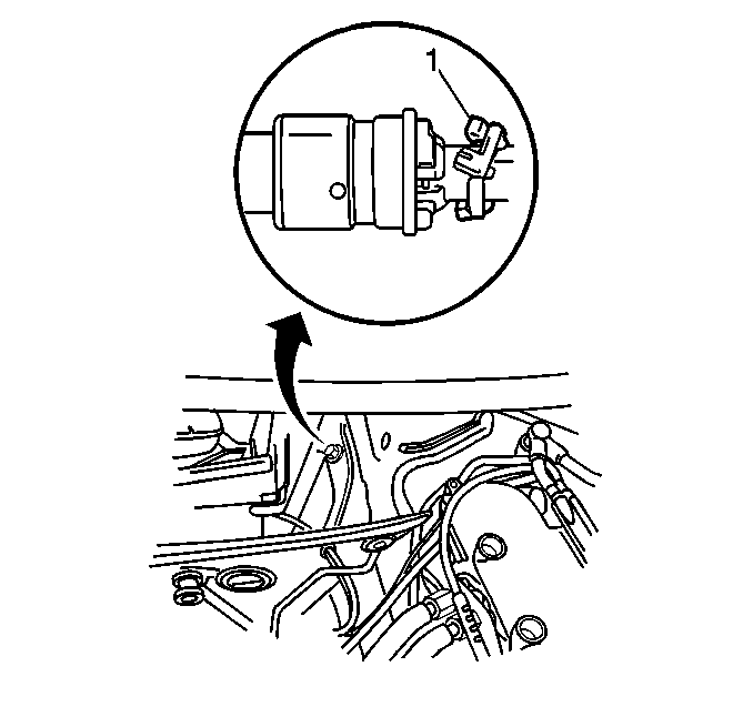
Important: Use care with the locking tabs on the quick connects, they break easily.
- Disconnect the heater hose quick connects from the heater core pipes.
| 29.1. | Raise the air inlet screen on the passenger side and open the
access door near the pollen filter. |
| 29.2. | Squeeze the tabs on the locking collar and pull back on the sleeve
to unlock. |
| 29.3. | Carefully pull back on the tabs to remove the quick connect from
the heater core pipes. |
| 29.4. | Discard the green assembly markers (1) if attached. |
- Remove the radiator (with the electric fan attached). Refer to
Radiator Replacement
in Engine Cooling.
- Remove the A/C compressor/condenser (HP) hose bracket screws where
the bracket connects near the driver's side frame rail.
- On the LH side engine compartment frame rail, remove the cooling
fan resistor screw and position the resistor out of the way to allow for added
engine removal clearances.
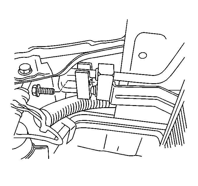
- Remove the condenser line
bolt from the condenser.
- Remove the condenser (HP) line from the condenser and plug the
connections to prevent A/C system contamination.
- Secure the HP A/C line to the engine with mechanic's wire to prevent
interference during engine removal.
- Disconnect the A/C system quick-connect near the low pressure
service valve and plug the connections to prevent A/C system contamination.
| 36.1. | Remove the protective cover. |
| 36.2. | Remove the snap ring. |
| 36.3. | Remove the A/C hose from the quick-connect. |
- Install the J 36857
to the two engine lift shackles on each side of the engine.
The lift shackles may be located under plastic protectors.
- Raise and support the vehicle. Refer to
Lifting and Jacking the Vehicle
in General Information.
- Remove the splash shield bolts.
- Remove the splash shield.
- Disconnect the A/C compressor electrical connector.
- Remove the transmission. Refer to
Transmission Replacement
in Automatic Transmission.
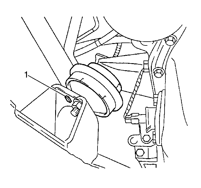
- Remove the engine mount
nuts. Note the orientation of the locator tab (1).
- Lower the vehicle.
- Connect the engine lift chains to the lift shackles.
- Remove the engine.
To enable extra clearances, remove the upper engine mount nuts and allow
the engine mounts to fall out of the way once the engine lift has assumed
the weight of the engine.
- Transfer parts as necessary.
- Install the motor mounts to the engine brackets, if removed.
Tighten
Tighten the upper motor mount nuts to 40 N·m (30 lb ft).
- Install the engine.
- Remove the engine lift chains from the lift shackles.
- Raise and support the vehicle.

Important: Ensure the guide pins (1) are in place and install the engine mount
nuts.
Notice: Use the correct fastener in the correct location. Replacement fasteners
must be the correct part number for that application. Fasteners requiring
replacement or fasteners requiring the use of thread locking compound or sealant
are identified in the service procedure. Do not use paints, lubricants, or
corrosion inhibitors on fasteners or fastener joint surfaces unless specified.
These coatings affect fastener torque and joint clamping force and may damage
the fastener. Use the correct tightening sequence and specifications when
installing fasteners in order to avoid damage to parts and systems.
- Install the lower
engine mount nuts.
Tighten
Tighten the lower engine mount nuts to 55 N·m (41 lb ft).
- Install the transmission. Refer to
Transmission Replacement
in Automatic Transmission.
- Connect the A/C compressor electrical connector.
- Install the splash shield.
- Install the splash shield bolts.
Tighten
Tighten the splash shield bolts until fully seated. Do not strip the
splash shield bolts.
- Lower the vehicle.
- Remove the J 36857
from the engine lift shackles and replace the plastic covers if removed.
- Reconnect the A/C system LP quick-connect (near the low pressure
service valve):
| 12.1. | Remove the plugs from the fittings. |
| 12.2. | Clean the fittings and the surrounding areas. |
| 12.3. | Install new O-rings. |
| 12.4. | Lubricate the O-rings with mineral oil, 525 viscosity. |
| 12.5. | Install the A/C hose into the quick-connect. |
| 12.6. | Install the snap ring. |
| 12.7. | Install the protective cover. |

- Reconnect the A/C system
HP condenser line to the condenser:
| 13.1. | Remove the plugs from the fittings. |
| 13.2. | Clean the fittings and the surrounding areas. |
| 13.3. | Install new O-rings. |
| 13.4. | Lubricate the O-rings with mineral oil, 525 viscosity. |
| 13.5. | Install the condenser line into the condenser. |
- Install the condenser line bolt.
Tighten
Tighten the condenser line bolt to 27 N·m (20 lb ft).
- On the LH side engine compartment frame rail, reposition the cooling
fan resistor and install the screw.
Tighten
Tighten the cooling fan resistor screw until fully seated and not stripped.
- Reposition the A/C compressor/condenser (HP) hose and bracket.
- Install the A/C compressor/condenser (HP) hose bracket screws
where the bracket connects near the driver's side frame rail.
Tighten
Tighten the A/C compressor/condenser hose bracket screws to 8 N·m
(71 lb in).
- Install the radiator (with the electric fan attached). Refer to
Radiator Replacement
in Engine Cooling.
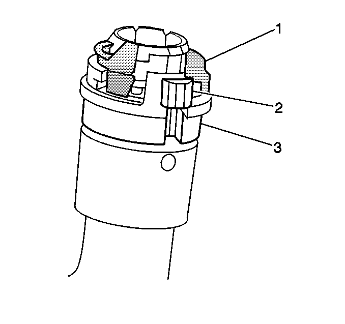
Important: Ensure the quick connects are fully seated and that the retaining sleeves
are pushed in to the locked position.
- Install the heater hose quick connects to the heater core pipes:
| 19.1. | Discard the green assembly marker (1), if not attached to the
quick connect. |
| 19.2. | Press the quick connects onto the heater core pipes. |
| 19.3. | Inspect that the quick connects are fully seated. |
| 19.4. | Squeeze the locking tabs (2) and push the retaining sleeve (3)
into the locked position. |
| 19.5. | Close and secure the access door near the pollen filter. |
| 19.6. | Lower the air inlet screen. |
- Install the electric heater water pump (with the hoses attached)
to the RH side of the engine compartment.
Tighten
Tighten the electric heater water pump screws until fully seated and
not stripped.
- Install the coolant reservoir hose and clamp to the coolant intake
pipe.

- Install the vacuum hose
to the hot water control valve.
- Install the vacuum hose to the purge valve located on the engine
ventilation chamber.
- Install the coolant hose and clamp to the throttle body.
Important: Counterhold the hoses, while tightening, to prevent damage to the fuel
rail.
- Install the fuel supply and return hoses.
Tighten
Tighten the fuel hose connections to 15 N·m (11 lb ft).

- Install the wiring harness
to the electrical center box and clip the relays in place.
- Install the ECM and secure in place.

- Install the vacuum hoses
(2) to the brake power booster hose.
- Install the brake booster threaded vacuum fitting (1) to the intake
plenum.
Tighten
Tighten the brake booster threaded vacuum fitting until fully seated.
Do not strip the brake booster threaded fitting.

- Install the power steering
pump discharge hose to the power steering pump.
Tighten
Tighten the power steering pump discharge hose connection to 28 N·m
(21 lb ft).

- Install the power steering
suction hose and clamp.
- Install the four power supply wires to the battery positive cable
end.
- Install the body ground wire to the battery negative cable end.

- Connect the large wiring
harness connectors (1).
- Install the air filter housing.
Ensure the air filter housing is fully seated in the rubber mounting
grommets.
- Install the air intake resonator. Refer to
Intake Air Resonator Replacement
in Engine Controls.
- Install the air inlet grilles. Refer to
Air Inlet Grille Panel Replacement
in Body Front
End.
- Install the wiper arms. Refer to
Windshield Wiper Arm Replacement
in Wipers Wash Systems.
- Install the hood. Refer to
Hood Replacement
in Body Front End.
- Install the battery and connect the cables. Refer to
Battery Replacement
in Engine Electrical.
- Recharge the A/C system. Refer to Refrigerant Recovery and Recharging
in HVAC with Automatic A/C.
- Fill the power steering system.
- Fill and bleed the cooling system. Refer to
Cooling System Draining and Filling
in Engine Cooling.
- Leak test the A/C system.
- Inspect for fluid and exhaust leaks.
- Bleed the power steering system.
- Reprogram the applicable accessories. Refer to
Reprogramming Accessories After Battery Disconnect
in Engine Electrical.


