Inspection and Diagnosis
A close examination of the differential prior to taking it apart often
reveals valuable information as to the extent and the type of repairs or adjustments
necessary. This information and the report of the malfunction provides a
basis for determining the degree of teardown required. Frequent causes
of axle noise are improper backlash, differential drive pinion gear bearing
preload, or a combination of these items. A few simple adjustments may be
all that are necessary to correct the problem. Inspect the following items
and record and analyze the results before removing the differential case
from the housing:
| • | Inspect the total differential preload. |
| • | Inspect the tooth contact pattern. |
Use care at all times to keep dirt and other foreign matter, such as
grinder shavings, dirt, or particulate contaminants, away from the differential
to prevent the possibility of subsequent failure.
Differential Ring Gear Tooth Nomenclature
The drive side of the gear tooth curves outward, or convex. The concave
side is the coast side. The end of the tooth nearest the center of the ring
gear is the toe end. The end of the tooth farthest away from the center
is the heel end. The toe end of the tooth is smaller than the heel end.
Tooth Contact Pattern Test
Tools Required
J 42178 Differential
Side and Pinion Alignment Kit
Important: It is very important that the tooth contact be tested before the differential
is taken apart. Variations in the differential and/or drive pinion gear inner
bearing may cause the drive gear to be too close, or too far away, from
the ring gear.
- Remove the differential. Refer to
Differential Carrier Assembly Replacement
.
- Clean all the dirt from the rear axle housing cover area before
removing the cover.
- Remove the rear axle housing cover. Refer to
Rear Axle Housing Cover and Gasket Replacement
.
- Wipe the axle lubricant out of the housing.
- Carefully clean each tooth of the ring gear.
- Use a medium stiff brush to apply gear marking compound, GM P/N 1052351
or equivalent, sparingly to all the ring gear teeth. When properly applied
the area of the differential drive pinion gear tooth contact is visible
when hand load is applied.
- Insert the J 42178
to the differential side bearing bore.
- Use a ratchet to hold theJ 42178
stationary.
- Rotate the pinion gear flange so that the ring gear rotates one
full revolution.
- Reverse the rotation so that the ring gear rotates one revolution
in the opposite direction.
- Observe the pattern on the ring gear teeth and compare to the
following:
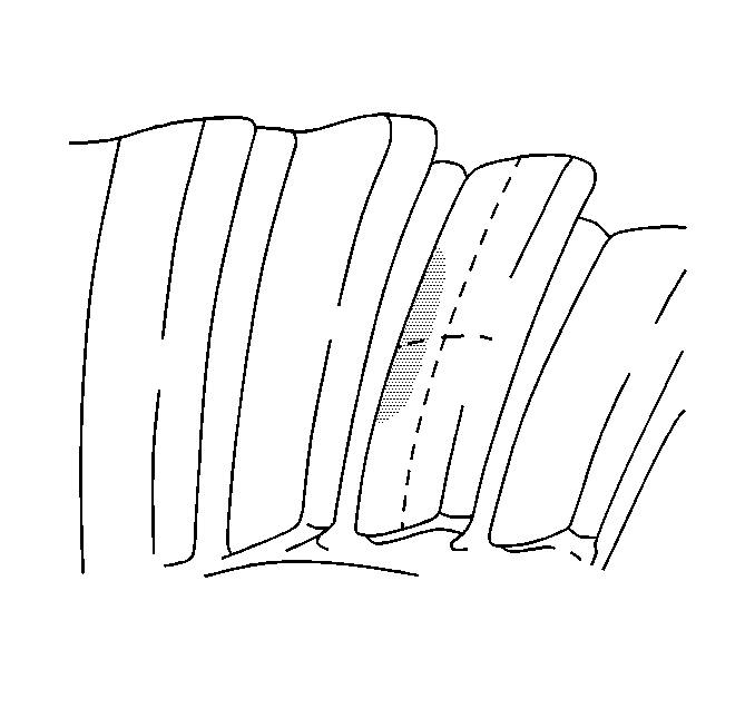
| • | Low Flank Contact (evident
by contact in the valley between the gear teeth): Decrease the pinion gear
bearing shim thickness, this will move the pinion gear out toward the ring
gear centerline. |
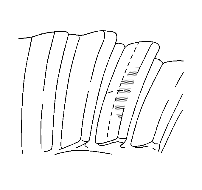
| • | High Face Contact (evident
by contact on the outboard edge of the gear tooth): Increase the pinion gear
bearing shim thickness, this will move the pinion gear in toward the ring
gear centerline. |
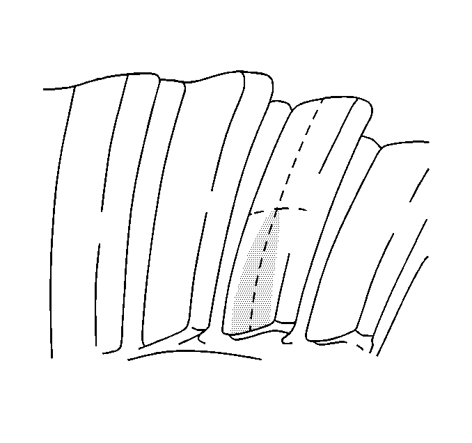
| • | Toe Contact (evident by
contact on the lower edge of the gear tooth): Increase the backlash, this
will move the area of pinion gear contact with the ring gear toward the
heel. |
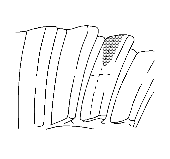
| • | Heel Contact (evident
by contact on the upper edge of the gear tooth): Decrease the backlash, this
will move the of pinion gear contact with the ring gear toward the toe. |
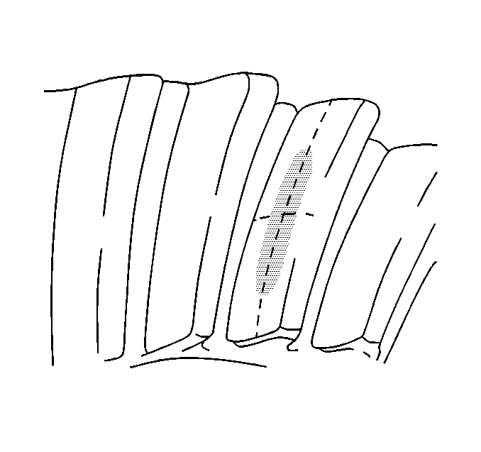
| • | Desired Contact Pattern:
Pinion gear contact in center of the ring gear tooth. |
- Reinstall the rear axle housing cover. Refer to
Rear Axle Housing Cover and Gasket Replacement
.
- Install the differential to the vehicle. Refer to
Differential Carrier Assembly Replacement
.
Adjustments Affecting Tooth Contact
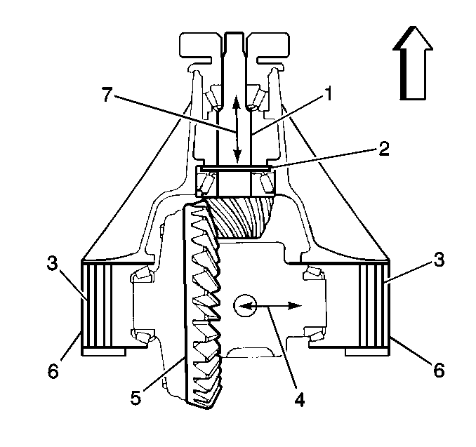
The following two adjustments
can be made which will affect the tooth contact pattern:
| • | The position of the drive pinion gear (1) in the housing |
The effects of bearing preloads are not readily apparent on hand-loaded
tooth contact pattern tests.
Backlash is adjusted by means of variable thickness adjuster rings (3).
They move the entire differential closer to, or farther from, the drive pinion
gear (1). These are also used to set the differential bearing
carrier bearing preload. If the thickness of the right snap ring (3)
is increased, along with decreasing the left snap ring (3), backlash (4)
increases. The backlash decreases if the left snap ring thickness is
increased, along with a decrease in the right snap ring thickness.
The position of the differential drive pinion gear is adjusted by increasing
or decreasing the drive pinion gear bearing shim (2) thickness between
the drive pinion gear inner bearing and the housing. A shim (2)
is used in the axle to compensate for manufacturing tolerances. Increasing
the thickness moves the drive pinion gear (1) closer to the centerline
of the ring gear (5). Decreasing the shim thickness moves the drive
pinion gear (1) farther away from the centerline of the ring gear (5).


