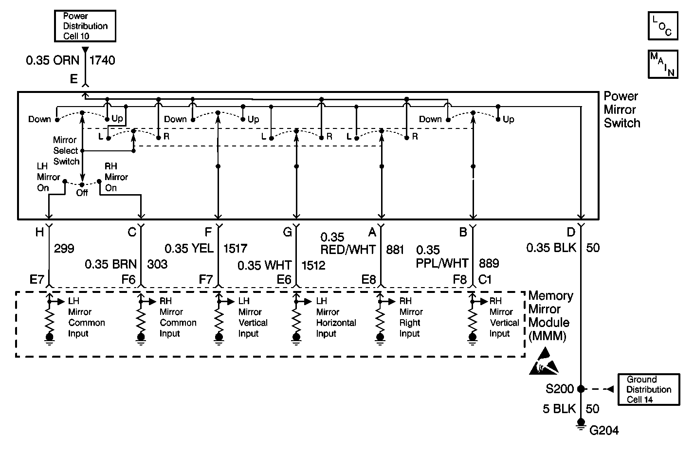
DTC B2143 Mirror Right Control Switch Circuit Malfunction DeVille

Circuit Description
The memory mirror module (MMM) receives inputs from the power mirror switch. The mirror select switch must be in either the left or the right position in order to operate the power mirror switch. The mirror switch is then operated in order to move one of the mirrors. When the mirror switch is operated, more than one input is sent from the power mirror switch to the MMM. If the MMM recognizes the input combination, the MMM moves the appropriate mirror in the requested direction. If the MMM does not recognize the input combination as a valid input, the MMM ignores that combination and does not move the mirrors.
When any mirror switch input continues to be active for 30 seconds after motion is requested ceased, the switch is considered shorted.
Conditions for Setting the DTC
The MMM sets the appropriate DTC any time the MMM detects a switch failure.
Action Taken When the DTC Sets
| • | The motor outputs being driven in response to the suspect switch are deactivated. |
| • | The MMM continues responding to valid inputs from the other positioning switches. |
| • | All of the memory recall commands are ignored. |
Conditions for Clearing the DTC
| • | The MMM does not detect the switch failure during the last monitoring cycle. |
| • | A history DTC will clear after 50 consecutive ignition cycles if the condition for the malfunction is no longer present. |
| • | Use the On-Board Clearing DTCs feature. |
| • | Use a scan tool. |
Diagnostic Aids
- Clear the DTCs and cycle the ignition.
- If the DTC resets, replace the power mirror switch.
Test Description
The numbers below refer to the step numbers on the diagnostic table.
-
Perform the Power Door Systems Diagnostic System Check
-
This step tests for a faulty power mirror switch.
-
Clear all of the DTCs following the completion of the repair procedure.
Step | Action | Value(s) | Yes | No |
|---|---|---|---|---|
Did you perform the Power Door Systems Diagnostic System Check? | -- | Go to Step 2 | ||
After 30 seconds, does the DTC reset? | -- | Go to Step 3 | ||
3 | Replace the power mirror switch. Is the repair complete? | -- | Go to Step 4 | -- |
Are all of the DTCs cleared? | -- | -- |
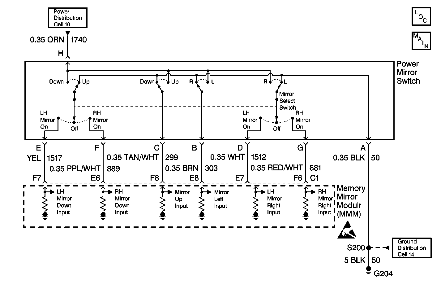
DTC B2143 Mirror Right Control Switch Circuit Malfunction Eldorado

Circuit Description
The memory mirror module (MMM) receives inputs from the power mirror switch. The mirror select switch must be in either the left or the right position in order to operate the power mirror switch. The mirror switch is then operated in order to move one of the mirrors. When the mirror switch is operated, more than one input is sent from the power mirror switch to the MMM. If the MMM recognizes the input combination, the MMM moves the appropriate mirror in the requested direction. If the MMM does not recognize the input combination as a valid input, the MMM ignores that combination and does not move the mirrors.
When any mirror switch input continues to be active for 30 seconds after motion is requested ceased, the switch is considered shorted.
Conditions for Setting the DTC
The MMM sets the appropriate DTC any time the MMM detects a switch failure.
Action Taken When the DTC Sets
| • | The motor outputs being driven in response to the suspect switch are deactivated. |
| • | The MMM continues responding to valid inputs from the other positioning switches. |
| • | All of the memory recall commands are ignored. |
Conditions for Clearing the DTC
| • | The MMM does not detect the switch failure during the last monitoring cycle. |
| • | A history DTC will clear after 50 consecutive ignition cycles if the condition for the malfunction is no longer present. |
| • | Use the On-Board Clearing DTCs feature. |
| • | Use a scan tool. |
Diagnostic Aids
- Clear the DTCs and cycle the ignition.
- If the DTC resets, replace the power mirror switch.
Test Description
The numbers below refer to the step numbers on the diagnostic table.
-
Perform the Power Door Systems Diagnostic System Check
-
This step tests for a faulty power mirror switch.
-
Clear all of the DTCs following the completion of the repair procedure.
Step | Action | Value(s) | Yes | No |
|---|---|---|---|---|
Did you perform the Power Door Systems Diagnostic System Check? | -- | Go to Step 2 | ||
After 30 seconds, does the DTC reset? | -- | Go to Step 3 | ||
3 | Replace the power mirror switch. Is the repair complete? | -- | Go to Step 4 | -- |
Are all of the DTCs cleared? | -- | -- |
