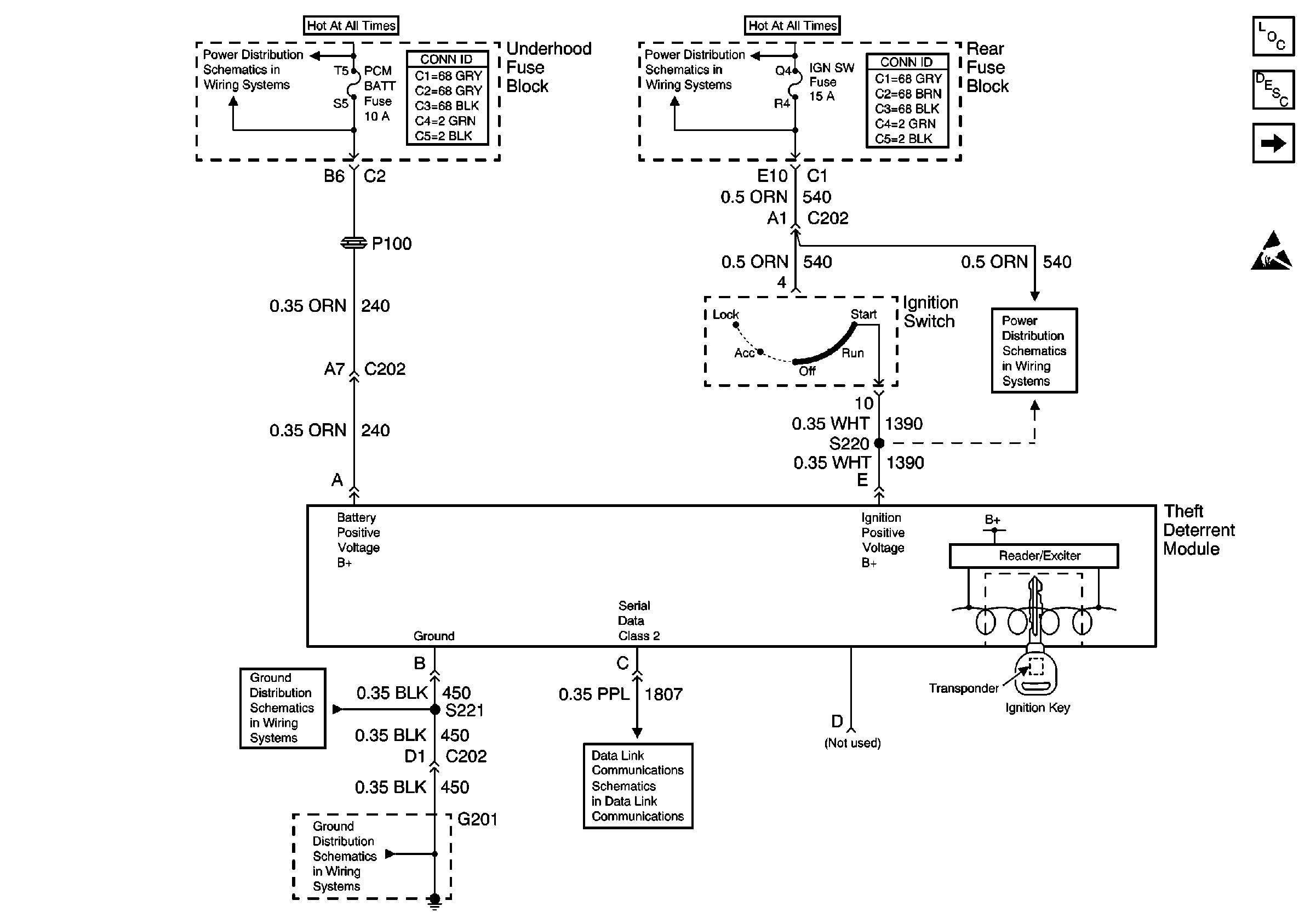
Refer to
VTD System

.
Circuit Description
The non volatile memory check sum and write error detection is handled inside the theft deterrent module. No external circuits are involved.
Conditions for Running the DTC
The microprocessor runs the program to detect a check sum error after each "power up". This program runs only if the DTCs B1327 and B1328 are not set as current DTCs.
Conditions for Setting the DTC
The microprocessor sets this DTC if it can not write to non volatile memory. The DTC is also set if the microprocessor can not run an accurate check sum on the non volatile memory.
Action Taken When the DTC Sets
| • | Stores a DTC B2734. |
| • | If the engine is running, the instrument cluster displays a SERVICE THEFT SYSTEM message. If the engine is not running STARTING DISABLED and REMOVE KEY message is displayed. |
| • | Security indicator is illuminated. |
| • | Prevent the engine from starting. |
Conditions for Clearing the MIL/DTC
The DTC clears when the microprocessor runs either a successful check sum test or a successful write to the non volatile memory.
Diagnostic Aids
| • | This DTC may be stored as a History DTC with out affecting the operation of the module. If stored only as a History DTC and not retrieved as a current DTC, do not replace the module. |
| • | If this DTC is retrieved as both a Current and History DTC, replace the module. |
Test Description
The numbers below refer to the step numbers on the diagnostic table.
-
Be sure that the original ignition key issued with the vehicle is used when performing the Theft Deterrent Diagnostic System Check.
-
The theft deterrent module must be programmed to the vehicle.
Step | Action | Value(s) | Yes | No |
|---|---|---|---|---|
Did you perform the Theft Deterrent Diagnostic System Check? | -- | Go to Step 2 | ||
2 |
Does the scan tool display the DTC as current? | -- | Go to Step 3 | Go to Diagnostic Aids |
Replace the theft deterrent module. Refer to Theft Deterrent Module Replacement . Important: Perform the Auto Learn Procedure for the theft deterrent module. Refer to Programming Theft Deterrent System Components .Did you complete the replacement? | -- | Go to Step 4 | -- | |
4 |
Does the DTC reset? | -- | Go to Step 2 | System OK |
