Removal Procedure
Tools Required
| • | J 34730 Fuel Pressure Gauge |
| • | J 41081 Fuel Injector Remover |
| • | J 37088-A Fuel Line Quick Connect Separator |
Notice:
• Remove the fuel rail assembly carefully in order to prevent damage
to the injector electrical connector terminals and the injector spray tips.
Support the fuel rail after the fuel rail is removed in order to avoid damaging
the fuel rail components. • Cap the fittings and plug the holes when servicing the fuel system
in order to prevent dirt and other contaminants from entering open pipes and
passages.
- Relieve fuel system pressure. Refer to Fuel Pressure Relief .
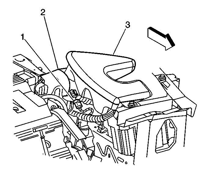
- Disconnect the IAT sensor connector (1) from the IAT sensor.
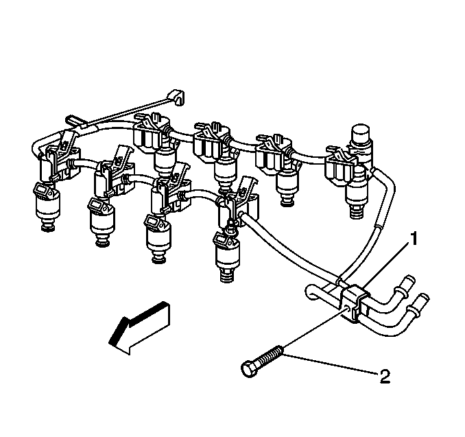
- Remove the fuel rail end-point bracket (1) retainer bolt (2) from the bracket.
- Remove the EGR pipe at throttle body spacer.
- Remove the brake booster vacuum hose at intake manifold vacuum fitting.
- Remove the front bank spark plug wires.
- Disconnect the Mass Air Flow (MAF) sensor (5) electrical connector (2) from the MAF sensor.
- Remove the MAF sensor. Refer to Mass Airflow Sensor Replacement .
- Disconnect the injector electrical connectors. Lay the harness aside.
- Remove the fuel rail ground wire (7) at rear cylinder head.
- Remove the fuel pressure regulator (1) from the fuel rail. Refer to Fuel Pressure Regulator Replacement .
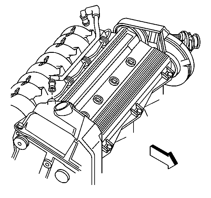
- Remove the crankcase ventilation vacuum hoses.
- Remove the fuel line retainers (2), (3) at the quick connect fittings.
- Disconnect the quick-connect fittings (2) at the fuel rail. Refer to Metal Collar Quick Connect Fitting Service or to Plastic Collar Quick Connect Fitting Service .
- Remove the throttle body mount bolts.
- Remove the throttle body. Refer to Throttle Body Assembly Replacement .
- Remove the throttle body spacer (3).
- Remove the throttle body O-ring seal.
- Release the locking tabs (8) on fuel rail by pushing toward center of intake manifold and pry each injector out of intake manifold using J 41081 .
- Remove the fuel rail assembly from the intake manifold.




Disassemble Procedure
- Remove the fuel injector harness from the intake manifold.
- Remove the clips (3) from the injectors (5) on the fuel rail.
- Remove the upper (6) and lower (4) seals from the injectors. Discard seals.


Assemble Procedure
- Lubricate the upper (6) and lower (4) injector O-rings with clean oil and install the O-rings on to the fuel injectors (5).
- Assemble the injectors to the fuel rail with new retainer clips (3).
- Assemble the injector harness to the intake manifold.


Installation Procedure
- Reinstall the fuel rail with injectors on to the intake manifold.
- Reinstall throttle body spacer (3).
- Install the new throttle body O-ring seal,
- Reinstall the throttle body (1). Refer to Throttle Body Assembly Replacement .
- Reinstall the throttle body mount bolts. Refer to
Notice: Use the correct fastener in the correct location. Replacement fasteners must be the correct part number for that application. Fasteners requiring replacement or fasteners requiring the use of thread locking compound or sealant are identified in the service procedure. Do not use paints, lubricants, or corrosion inhibitors on fasteners or fastener joint surfaces unless specified. These coatings affect fastener torque and joint clamping force and may damage the fastener. Use the correct tightening sequence and specifications when installing fasteners in order to avoid damage to parts and systems.
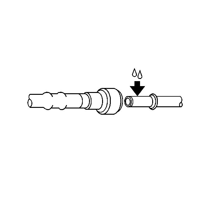
in Cautions and Notices. - Apply a few drops of clean engine oil to the male ends of the engine fuel rail inlet and outlet pipes.
- Connect the quick-connect fittings to fuel rail. Refer to Metal Collar Quick Connect Fitting Service or to Plastic Collar Quick Connect Fitting Service .
- Reinstall the fuel line retainers (2,3) at the quick connect fittings.
- Reinstall the fuel pressure regulator. Refer to Fuel Pressure Regulator Replacement .
- Reinstall the crankcase ventilation vacuum hoses.
- Install the fuel rail ground wire (7) at rear cylinder head.
- Connect the injector harness and injector electrical connectors.
- Reinstall the front bank spark plug wires.
- Connect the brake booster vacuum hose at intake manifold vacuum fitting.
- Connect the EGR pipe at throttle body spacer.
- Install the fuel rail end-point bracket (1) retainer bolt (2).
- Connect the IAT sensor connector (1) to the IAT sensor.
- Reinstall the MAF sensor (2). Refer to Mass Airflow Sensor Replacement .
- Connect the MAF sensor electrical connector to the MAF.
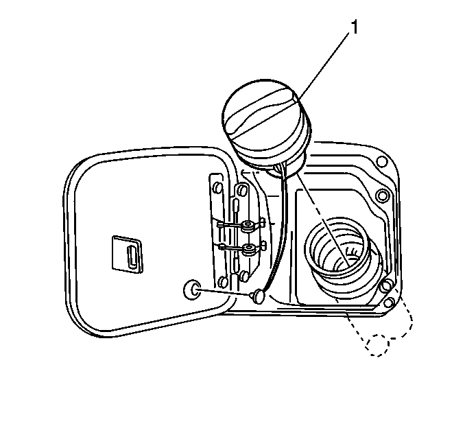
- Tighten fuel filler cap (1).
- Connect the negative battery cable. Refer to Battery Negative Cable Disconnection and Connection in Engine Electrical.
- Inspect for fuel leaks.
- Install the rear seat cushion. Refer to Rear Seat Cushion Replacement in Seats.
- Install the intake manifold sight shield.


Tighten
Tighten the throttle body mount bolts to 12 N·m (106 lb in).


Tighten
Tighten the fuel rail ground wire bolt to 11 N·m (97 lb in).


Tighten
Tighten the EGR pipe bolt to 28 N·m (21 lb in).

Tighten
Tighten the bolt to 4 N·m (35 lb in).

| 22.1. | Turn the ignition switch ON for 2 seconds. |
| 22.2. | Turn the ignition switch OFF for 10 seconds. |
| 22.3. | Turn the ignition switch ON. |
| 22.4. | Check for fuel leaks. |
Tighten
Tighten the nuts to 3 N·m (27 lb in).
