For 1990-2009 cars only
Removal Procedure
- Disconnect the negative battery cable.
- Disable the SIR system. Refer to Disabling the SIR System in Restraints.
- Remove the steering wheel. Refer to Steering Wheel Replacement .
- Remove the kneebolster. Refer to Driver Knee Bolster Panel Replacement in Instrument Panels and Gauges.
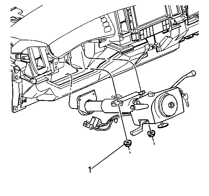
- Remove the two nuts (1) securing the steering column to the instrument panel.
- Lower the column.
- Remove the tilt lever handle.
- Remove the upper and lower shrouds. Refer to Trim Covers, Shift Lever Seal Replacement - Off Vehicle .
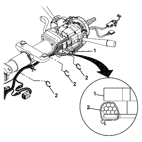
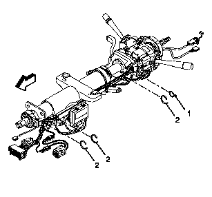
- Remove the two wire harness straps.
- Remove one wire harness strap from the steering column tilt head assembly.
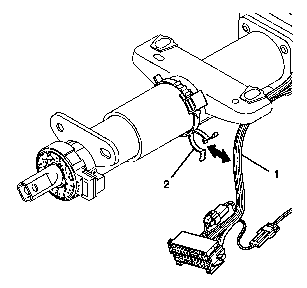
- Remove the wire harness assembly (1) from the wire harness strap (2).
- When working on the power tilt and telescope column remove three wire harness straps (1).
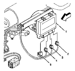
- When working on the power tilt and telescope column remove the green (5), brown (4), natural (3)and the black (2), connectors from the E&C interface module assembly.
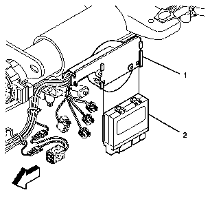
- When working on the power tilt and telescope column remove the E&C interface module assembly (2) from the lower wire shield (1).
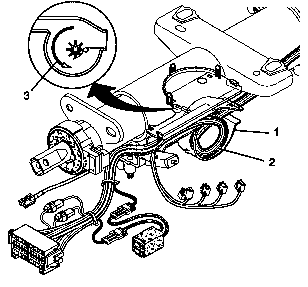
- When working on the power tilt and telescope column open the lower wire shield (1) to remove the wire harness assembly (2), In the lower wire shield (1) notice which direction (3) and placement the wires are in.
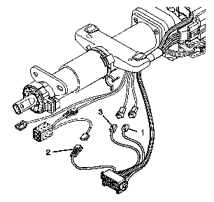
- Remove the blue (1), black (2) and gray (3) connectors of the turn signal and multifunction switch assembly.
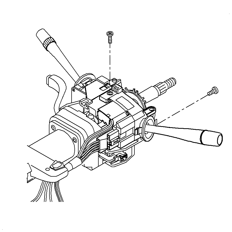
- Remove the two TORX® screws (1).
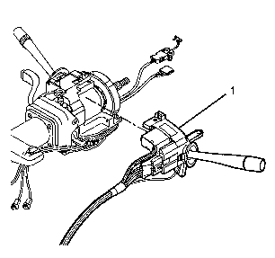
- Remove the turn signal and multifunction switch assembly (1).
Caution: Refer to Battery Disconnect Caution in the Preface section.
Installation Procedure
- Install the turn signal and multifunction switch assembly (1).
- Install the two torx® screws (1).
- Install the wire harness assembly along the steering column jacket assembly.
- Install the blue (1), black (2) and gray (3) connectors of the turn signal and multifunction switch assembly.
- Insert the wire harness assembly (1) into the wire strap holder (2).
- Install the two wire harness straps (2), Install one wire harness strap ( 2) to the steering column tilt head assembly (1).
- When working on the power tilt and telescope column install the wire harness assembly (2) into the lower wire shield (1) , In the lower wire shield (1) notice the direction (3) and placement the wires go in.
- When working on the power tilt and telescope column slide the E&C interface module assembly (2) into the wire shield (1).
- When working on the power tilt and telescope column install the green (5), brown (4), natural (3) and black (2) connectors into the E&C interface module assembly (1).
- When working on the power tilt and telescope column install the three wire straps (2) onto the wire harness assembly.
- Install the wire harness strap (1) into the steering column tilt head assembly.
- Install the upper and lower shrouds. Refer to Trim Covers, Shift Lever Seal Replacement - Off Vehicle .
- Remove the two nuts (1) securing the steering column to the instrument panel.
- Install the tilt lever .
- Install the steering wheel. Refer to Steering Wheel Replacement .
- Install the kneebolster. Refer to Driver Knee Bolster Panel Replacement in Instrument Panels and Gauges.
- Install the negative battery cable. Refer to Battery Disconnect Caution in Cautions and Notices.
- Enabale the SIR. Refer to Enabling the SIR System in Restraints.

Important: The electrical contact must rest on the turn signal cancel cam assembly.

Tighten
Tighten the screws to 7 N·m(62 lb in).


