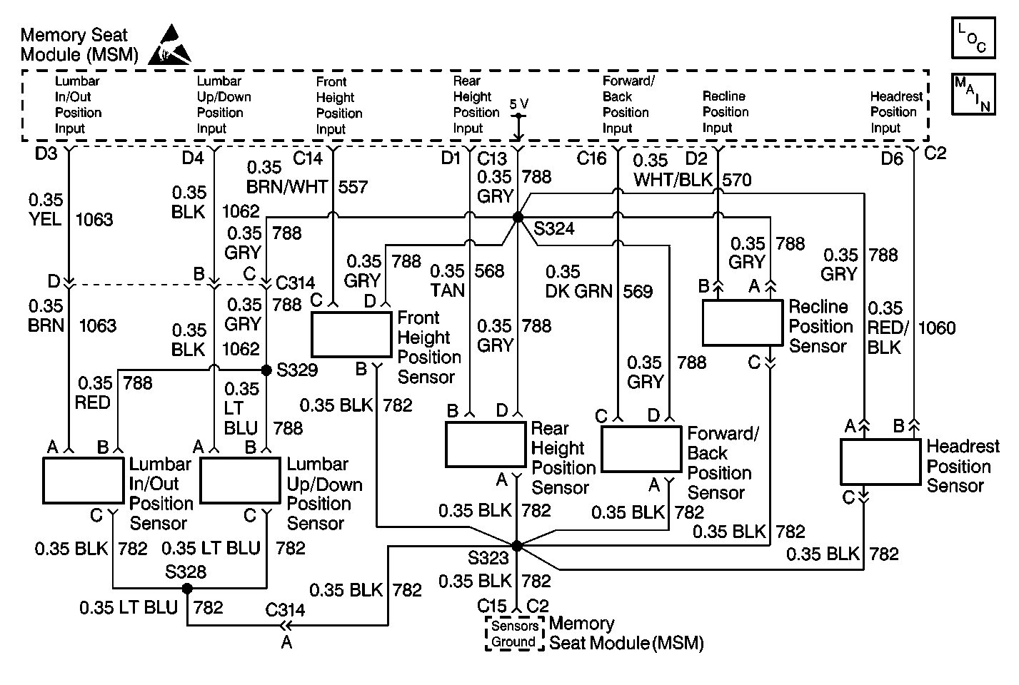
Circuit Description
The memory seat module (MSM) receives inputs from the lumbar in/out position sensor during memory recall and memory set functions. The potentiometer in the position sensor varies in resistance as the motor moves the lumbar support in and out within the seat back. The MSM receives a variable voltage input depending on the resistance of the potentiometer. During memory set, the MSM records the voltage across the lumbar in/out potentiometer. During memory recall, the MSM moves the lumbar in/out motor until the voltage across the potentiometer matches the voltages stored in memory. The lumbar support is not moved during the easy exit function. During normal operation, the lumbar in/out position sensor is checked against out-of-range voltage limits.
Conditions for Setting the DTC
| • | The MSM will set the DTC B2119 any time it detects that the lumbar in/out sensor input voltage is out of range (less than 0.25 volts or greater than 4.75 volts). |
| • | DTC B2119 will set only if DTC B1982 MSM or DTC B1983 MSM is not current. |
Action Taken When the DTC Sets
When DTC B2119 is set as current, the Memory Seat Module (MSM) will disable the lumbar in/out motor during memory recall operation. The lumbar in/out motor will remain enabled for manual positioning.
Conditions for Clearing the DTC
| • | The MSM detects that the lumbar in/out position sensor input is within the valid voltage range. |
| • | Use the On-Boards clearing DTCs feature. |
| • | Use a scan tool. |
Test Description
The numbers below refer to the step numbers on the diagnostic table:
-
Perform the Power Seat Systems Diagnostic System Check before continuing with the diagnosis of this DTC.
-
Multiple position sensor DTCs set indicates a concern with the reference wiring or memory seat module (MSM). Only one position sensor DTC set indicates a concern with the position sensor and wiring.
-
Clear all DTCs after the repair procedure is complete.
Step | Action | Value(s) | Yes | No |
|---|---|---|---|---|
Was the entire Power Seat Systems Diagnostic System Check performed? | -- | |||
Were there any other position sensor DTCs set? | -- | |||
3 |
Important:: When reconnecting the position sensor connector, be sure that the connector is connected in the proper direction. It is possible to reverse the connector and cause improper memory operation. Is the resistance within the specified range? | 9000 ohms - 11,000 ohms | ||
4 | Connect a DMM from the lumbar in/out position sensor cavity A (BRN) to cavity C (BLK). Is the resistance within the specified range? | 500 ohms - 9500 ohms | ||
5 |
Is the resistance less than the specified value? | 5 ohms | ||
6 | Connect a DMM from the lumbar in/out position sensor connector cavity C (BLK) to the MSM connector C2 cavity C15 (BLK). Is the resistance less than the specified value? | 5 ohms | ||
7 | Connect a DMM from the lumbar in/out position sensor connector cavity A (BRN) to ground. Is the resistance less than the specified value? | 5 ohms | ||
8 | Connect a DMM from the lumbar in/out position sensor connector cavity A (BRN) to the MSM connector C2 cavity D3 (YEL). Is the resistance less than the specified value? | 5 ohms | ||
9 |
Is the resistance less than the specified value? | 5 ohms | ||
10 | Connect a DMM from the lumbar in/out position sensor connector cavity B (RED) to the MSM connector C2 cavity C13 (GRY). Is the resistance less than the specified value? | 5 ohms | ||
11 | Connect a DMM from the lumbar in/out position sensor connector cavity C (BLK) to the MSM connector C2 cavity C15 (BLK). Is the resistance less than the specified value? | 5 ohms | ||
12 | Replace the lumbar in/out position sensor. Refer to Lumbar Component Replacement - Power . Is the lumbar in/out position sensor replacement complete? | -- | -- | |
13 | Repair the open in CKT 788 (RED) between S329 and the lumbar in/out position sensor. Refer to Wiring Repairs in Wiring Systems. Is the circuit repair complete? | -- | -- | |
14 | Repair the open in CKT 782 (BLK) between S328 and the lumbar in/out position sensor. Refer to Wiring Repairs in Wiring Systems. Is the circuit repair complete? | -- | -- | |
15 | Repair the short in CKT 1063 (YEL) or (BRN). Refer to Wiring Repairs in Wiring Systems. Is the circuit repair complete? | -- | -- | |
16 | Repair the open in CKT 1063 (YEL) or (BRN) between the MSM and the lumbar in/out position sensor. Refer to Wiring Repairs in Wiring Systems. Is the circuit repair complete? | -- | -- | |
17 | Repair the short in CKT 788 (GRY) or (RED). Refer to Wiring Repairs in Wiring Systems. Is the circuit repair complete? | -- | -- | |
18 | Repair the open in CKT 788 (GRY) between the MSM and S324. Refer to Wiring Repairs in Wiring Systems. Is the circuit repair complete? | -- | -- | |
19 | Repair the open in CKT 782 (BLK) between the MSM and the S323. Refer to Wiring Repairs in Wiring Systems. Is the circuit repair complete? | -- | -- | |
20 | Replace the memory seat module (MSM). Refer to Memory Seat Control Module Replacement . Is the MSM replacement complete? | -- | -- | |
Are all DTCs cleared? | -- | -- |
