Air Inlet Actuator Replacement LHD
Removal Procedure
- Remove the instrument panel (IP) compartment. Refer to Instrument Panel Compartment Replacement in Instrument Panel, Gauges and Console.
- Remove the right sound insulator. Refer to Instrument Panel Insulator Panel Replacement - Right Side in Instrument Panel, Gauges and Console.
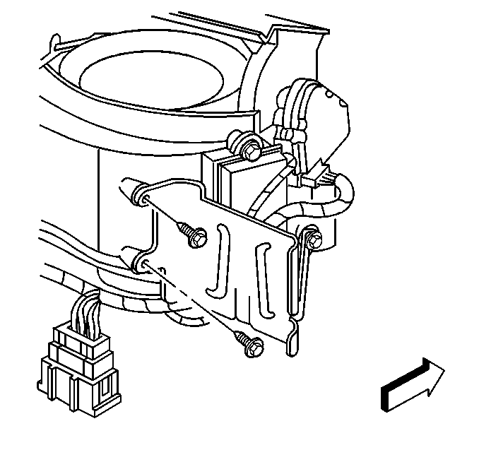
- Remove the dash integration module (DIM) from the bracket. Refer to Dash Integration Module Replacement in Body Control System.
- Remove the rear 2 DIM module bracket fasteners.
- Reposition the DIM module bracket in order to gain access to the air inlet actuator.
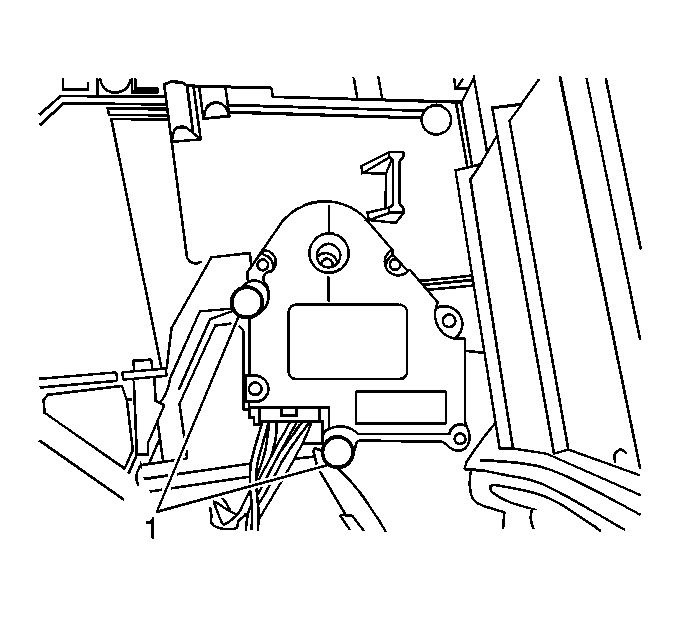
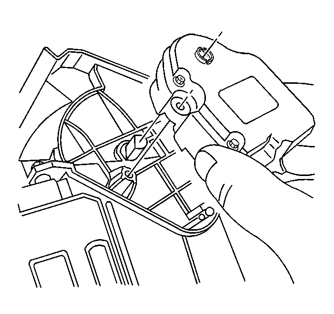
- Remove the air inlet actuator retaining fasteners (1).
- Remove the electrical connector from the air inlet actuator.
- Remove the air inlet actuator.
Installation Procedure
- Install the air inlet actuator.
- Install the air inlet actuator retaining fasteners (1).
- Install the electrical connector to the air inlet actuator.
- Position the DIM module bracket to its original position.
- Install the rear 2 DIM module bracket retaining fasteners.
- Install the DIM module into the bracket. Refer to Dash Integration Module Replacement in Body Control System.
- Install the right sound insulator. Refer to Instrument Panel Insulator Panel Replacement - Right Side in Instrument Panel, Gauges and Console.
- Install the IP compartment. Refer to Instrument Panel Compartment Replacement in Instrument Panel, Gauges and Console.
Notice: Use the correct fastener in the correct location. Replacement fasteners must be the correct part number for that application. Fasteners requiring replacement or fasteners requiring the use of thread locking compound or sealant are identified in the service procedure. Do not use paints, lubricants, or corrosion inhibitors on fasteners or fastener joint surfaces unless specified. These coatings affect fastener torque and joint clamping force and may damage the fastener. Use the correct tightening sequence and specifications when installing fasteners in order to avoid damage to parts and systems.
Tighten
Tighten the fasteners to 1.4 N·m (12 lb in).
Notice: Use the correct fastener in the correct location. Replacement fasteners must be the correct part number for that application. Fasteners requiring replacement or fasteners requiring the use of thread locking compound or sealant are identified in the service procedure. Do not use paints, lubricants, or corrosion inhibitors on fasteners or fastener joint surfaces unless specified. These coatings affect fastener torque and joint clamping force and may damage the fastener. Use the correct tightening sequence and specifications when installing fasteners in order to avoid damage to parts and systems.
Tighten
Tighten the fasteners to 1.4 N·m(12 ft lb).
Air Inlet Actuator Replacement RHD
Removal Procedure
- Remove the instrument panel (IP) compartment. Refer to Instrument Panel Compartment Replacement in Instrument Panel, Gauges and Console.
- Remove the left sound insulator. Refer to Instrument Panel Insulator Panel Replacement - Left Side in Instrument Panel, Gauges and Console.
- Remove the dash integration module (DIM) from the bracket. Refer to Dash Integration Module Replacement in Body Control System.
- Remove the rear 2 DIM module bracket fasteners.
- Reposition the DIM module bracket in order to gain access to the air inlet actuator.
- Remove the electrical connector from the air inlet actuator.
- Remove the air inlet actuator retaining fasteners (1).
- Remove the air inlet actuator.
Installation Procedure
- Install the air inlet actuator.
- Install the air inlet actuator retaining fasteners (1).
- Install the electrical connector to the air inlet actuator.
- Position the DIM module bracket to its original position.
- Install the rear 2 DIM module bracket retaining fasteners.
- Install the DIM module into the bracket. Refer to Dash Integration Module Replacement in Body Control System.
- Install the left sound insulator. Refer to Instrument Panel Insulator Panel Replacement - Left Side in Instrument Panel, Gauges and Console.
- Install the IP compartment. Refer to Instrument Panel Compartment Replacement in Instrument Panel, Gauges and Console.
Notice: Use the correct fastener in the correct location. Replacement fasteners must be the correct part number for that application. Fasteners requiring replacement or fasteners requiring the use of thread locking compound or sealant are identified in the service procedure. Do not use paints, lubricants, or corrosion inhibitors on fasteners or fastener joint surfaces unless specified. These coatings affect fastener torque and joint clamping force and may damage the fastener. Use the correct tightening sequence and specifications when installing fasteners in order to avoid damage to parts and systems.
Tighten
Tighten the fasteners to 1.4 N·m (12 lb in).
Notice: Use the correct fastener in the correct location. Replacement fasteners must be the correct part number for that application. Fasteners requiring replacement or fasteners requiring the use of thread locking compound or sealant are identified in the service procedure. Do not use paints, lubricants, or corrosion inhibitors on fasteners or fastener joint surfaces unless specified. These coatings affect fastener torque and joint clamping force and may damage the fastener. Use the correct tightening sequence and specifications when installing fasteners in order to avoid damage to parts and systems.
Tighten
Tighten the fasteners to 1.4 N·m (12 lb in).
