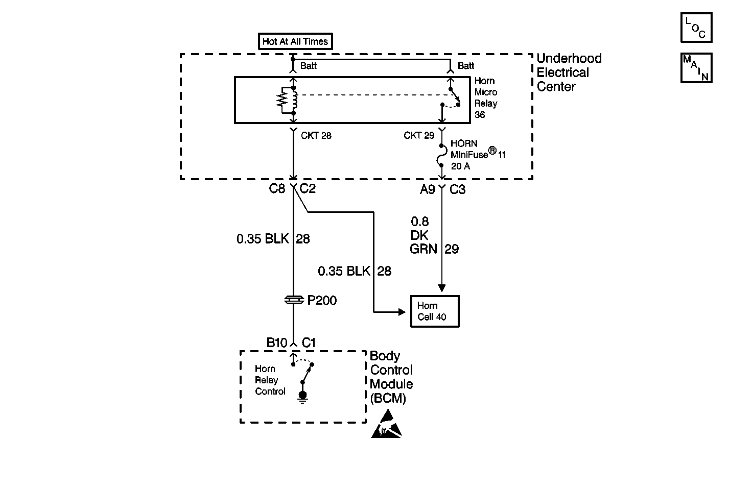
Circuit Description
The horn circuit is part of a standard horn system except for the addition of a relay and the BCM providing a control circuit. The BCM can ground CKT 28 in order to energize the relay and turn ON the horns, allowing the horns to be used for Universal Theft Deterrent (UTD) and Remote Function Actuation (RFA) functions. The BCM monitors the voltage level on the horn control circuit. When the BCM commands the relay ON, the voltage level on the control circuit should be low. When the relay is OFF, the voltage level should be high. If the BCM detects a voltage level other than expected, a malfunction is present and a DTC will set.
Conditions for Setting the DTC
| • | The BCM detects a low voltage level (an open or a short to ground) in CKT 28. |
| • | The BCM can only test for this condition with the horn relay de-energized. |
| • | The condition must be present for 2 seconds. |
Action Taken When the DTC Sets
| • | Stores a DTC B2527 in the BCM memory. |
| • | No driver warning message will be displayed for this DTC. |
Conditions for Clearing the DTC
| • | This DTC requires an ignition cycle in order to change from current to history. |
| • | The BCM no longer detects a high voltage level in CKT 28 only with the horn relay de-energized. |
| • | A history DTC will clear after 50 consecutive ignition cycles if the condition for the malfunction is no longer present. |
| • | Use the IPC clearing DTCs feature. |
| • | Use a scan tool. |
Diagnostic Aids
| • | The following conditions may cause an intermittent malfunction: |
| - | There is an intermittent open or short to ground in CKT 28. |
| - | There is high resistance in the relay coil. |
| - | There is a short to ground in the horn pad. |
| - | There are poor connections at the BCM, the underhood electrical center, or the horn relay terminals. |
| - | The horn relay is open or shorted to ground internally. |
| • | If CKT 28 is shorted to ground, the horn will remain ON at all times. If CKT 28 is open, the BCM may not be able to provide horn control functions, but the horn may still operate correctly depending on where the open circuit is located. |
| • | The horn relay may be installed in the I/P electrical center in two directions and still function properly. Refer to Power Distribution Schematics in Wiring Systems for electrical center identification. |
| • | If the DTC is a history DTC, the problem may be intermittent. Perform the tests shown while moving related wiring and connectors. This can often cause the malfunction to occur. Refer to Intermittents and Poor Connections Diagnosis . |
Test Description
The numbers below refer to the step numbers on the diagnostic table:
-
This test determines if there is an open in the U/H electrical center or fuse.
-
This test checks the horn relay control circuit by using a scan tool to command the BCM to energize the horn relay ON and OFF.
-
This test determines if there is an open or short to ground in CKT 28.
-
This test determines if there is a short to ground in the horn switch.
Step | Action | Value(s) | Yes | No |
|---|---|---|---|---|
1 | Were you sent here from the BCM Diagnostic System Check? | -- | ||
Is the test light ON? | -- | |||
Does the test light turn ON and OFF with each command? | -- | |||
Check for an open or short to ground in CKT 28. Was a problem found and repaired? | -- | |||
Check for a short to ground in the horn switch. Was a problem found and repaired? | -- | |||
6 | Check for poor connections at the horn relay. Was a problem found and repaired? | -- | ||
7 | Check for poor connections at the harness connector of the body control module. Was a problem found and repaired? | -- | ||
8 |
Is the circuit repair complete? | -- | -- | |
9 | Replace the horn relay. Is the replacement complete? | -- | -- | |
10 |
Is the replacement complete? | -- | -- | |
11 |
Is the repair complete? | -- | -- |
