GM Service Manual Online
For 1990-2009 cars only
Figure 1:

Cell 11: Audio Alarm Module, Dome Lamp, Radio, DLC, Luggage Compartment Lamp, Powertrain Control Module (PCM), Stoplamp Switch


Object Number: 463212  Size: FS
Power and Grounding Components
Data Link Connector Circuit Description
Cell 11: Turn Signal/Combination Switch, Instrument Panel Cluster Assembly, Power Door Lock Control Module
Handling ESD Sensitive Parts Notice
Power Distribution Schematics
Figure 2:

Cell 11: Turn Signal/Combination Switch, Instrument Panel Cluster Assembly, Power Door Lock Control Module


Object Number: 463219  Size: FS
Power Distribution Schematics
Handling ESD Sensitive Parts Notice
Power and Grounding Components
Data Link Connector Circuit Description
Fuse Block Details
Cell 11: Audio Alarm Module, Dome Lamp, Radio, DLC, Luggage Compartment Lamp, Powertrain Control Module (PCM), Stoplamp Switch
Figure 3:

Cell 11: Fuse Block Details, IG Coil, Ign Coils 1 and 2
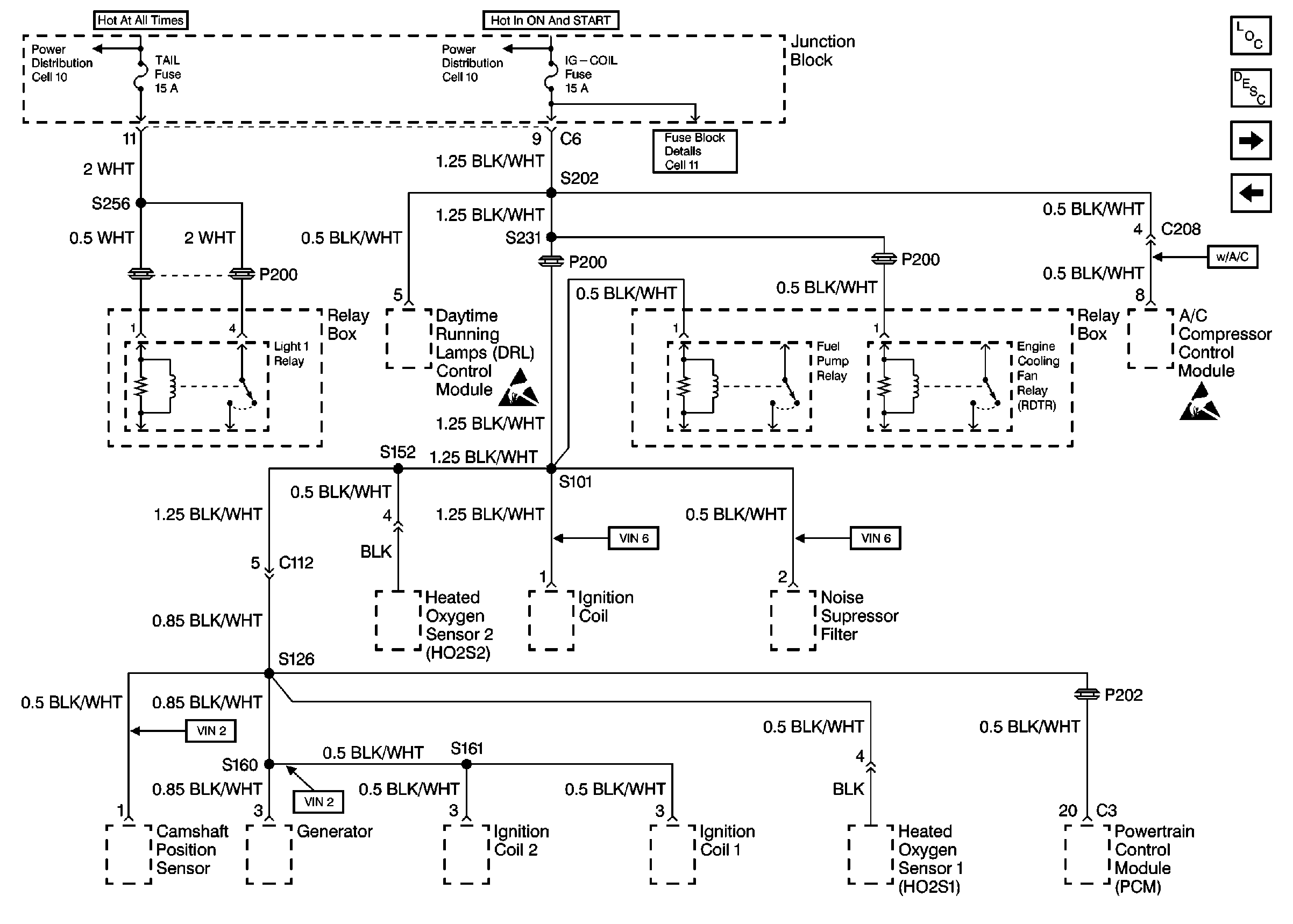

Object Number: 464972  Size: FS
Power Distribution Schematics
Power and Grounding Components
Power and Grounding Description
Cell 11: Turn Signal/Combination Switch, Instrument Panel Cluster Assembly, Power Door Lock Control Module
Cell 11: Audio Alarm Module, Instrument Panel Cluster Assembly
Handling ESD Sensitive Parts Notice
Figure 4:

Cell 11: Audio Alarm Module, Instrument Panel Cluster Assembly


Object Number: 463230  Size: FS
Power and Grounding Components
Data Link Connector Circuit Description
Cell 11: Turn Signal/Combination Switch, Rear Wiper/Washer Switch, Front and Rear Wiper Motor, Backup Lamp Switch, Transaxle Range Switch, Turn Signal/Combination Switch
Fuse Block Details
Handling ESD Sensitive Parts Notice
SIR Handling Caution
Fuse Block Schematics
Power Distribution Schematics
Figure 5:

Cell 11: Turn Signal/Combination Switch, Rear Wiper/Washer Switch, Front and Rear Wiper Motor, Backup Lamp Switch, Transaxle Range Switch, Turn Signal/Combination Switch


Object Number: 463235  Size: FS
Power and Grounding Components
Data Link Connector Circuit Description
Cell 11: Electronic Brake Control Module (EBCM)
Cell 11: Audio Alarm Module, Instrument Panel Cluster Assembly
Power Distribution Schematics
Figure 6:

Cell 11: Electronic Brake Control Module (EBCM)


Object Number: 463244  Size: FS
Handling ESD Sensitive Parts Notice
Power and Grounding Components
Data Link Connector Circuit Description
Cell 11: Fuse Box
Cell 11: Turn Signal/Combination Switch, Rear Wiper/Washer Switch, Front and Rear Wiper Motor, Backup Lamp Switch, Transaxle Range Switch, Turn Signal/Combination Switch
Figure 7:

Cell 11: Fuse Box


Object Number: 463253  Size: FS
Power and Grounding Components
Data Link Connector Circuit Description
Cell 11: Electronic Brake Control Module (EBCM)
Power Distribution Schematics