System Overview
The fuel tank stores the fuel supply. An electric fuel pump, located in the fuel tank within the modular fuel sender assembly, pumps fuel through an in-line fuel filter to the fuel rail assembly. The pump provides fuel pressure greater than is needed by the injectors. The fuel pressure regulator keeps fuel available to the injectors at a regulated pressure. A separate fuel pipe is used to return fuel to the fuel tank.
Fuel Tank

The fuel tank is used to store fuel for the vehicle. The tank is located in the rear of the vehicle and is held in place by two metal straps that are attached to the underbody. The fuel tank is made of steel and is coated internally with a special corrosion inhibitor. Due to the internal coating of the fuel tank, the fuel tank is not repairable. The fuel tank shape includes a reservoir in order to maintain a constant supply of fuel around the fuel pump strainer during low fuel conditions and aggressive vehicle maneuvers. A fuel tank filler pipe check-valve tube is attached to the fuel tank and extends from the fuel tank inlet to the reservoir. The fuel tank filler pipe check-valve is located inside the fuel tank filler pipe check-valve tube and prevents fuel from splashing back out of the fuel tank filler pipe during refueling.
Fuel Tank Filler Pipe

In order to prevent refueling with leaded fuel, the fuel tank filler pipe (2) has a built-in restrictor and deflector. The fuel tank filler pipe is connected to the fuel tank filler extension (1) by clamps.
Fuel Tank Filler Pipe Cap
Notice: Use a fuel tank filler pipe cap with the same features as the original when a replacement is necessary. Failure to use the correct fuel tank filler pipe cap can result in a serious malfunction of the fuel system.
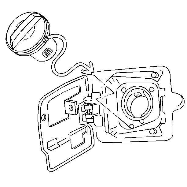
The fuel tank filler pipe is equipped with a screw type fuel tank filler pipe cap. A built-in torque-limiting device prevents over tightening of the fuel tank filler pipe cap. In order to install the fuel tank filler pipe cap, turn the fuel tank filler pipe cap clockwise until a clicking noises is heard. The clicking noises signal that the correct torque has been reached and that the fuel tank filler pipe cap is fully seated. A fuel filler cap that is not fully seated, may cause a malfunction in the emission system.
The Enhanced EVAP fuel tank pipe cap has a tether connected to the fuel filler door.
Modular Fuel Sender Assembly

The Modular Fuel Sender Assembly consists of the following major components: fuel sender strainer, fuel pump strainer, roll-over valve, fuel level sensor, and fuel tank pressure sensor.
Fuel Level Sensor
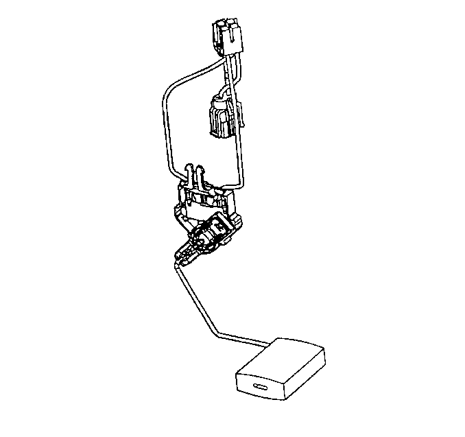
The Fuel Level Sensor consists of the following components: float, the wire float arm, and the ceramic resistor card. The Fuel Level Sensor is mounted on the Modular Fuel Sender Assembly and is used as an input to the PCM. The PCM uses this information as a fuel level input for Various diagnostics. The PCM controls the Fuel Level Gauge by grounding the Fuel Gauge Control circuit.
Fuel Pump
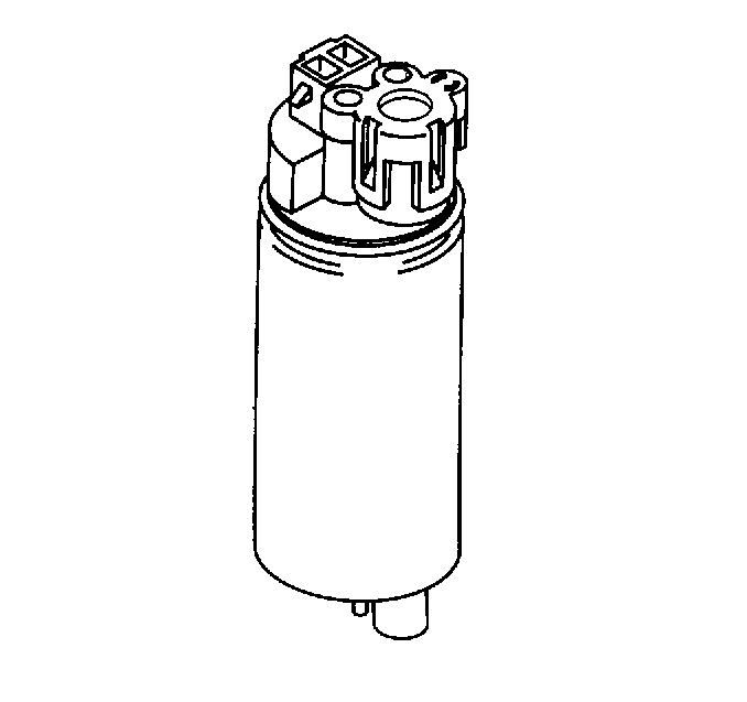
A high pressure gerotor fuel pump is mounted to the fuel sender inside the fuel tank. The fuel is pumped to the engine at a specified flow and pressure through the fuel pump. Excess fuel is returned to the fuel tank by a return pipe. The fuel pump delivers a constant flow of fuel to the engine even during low fuel conditions and aggressive vehicle maneuvers.
The electric fuel pump operation is controlled by the Powertrain Control Module (PCM) through a fuel pump relay. Refer to Fuel Pump Electrical Circuit Diagnosis .
Fuel Pump Strainer

A woven plastic fuel pump strainer is attached to the lower end of the fuel pump in the fuel tank. The functions of the fuel pump strainer are to filter contaminants and to wick fuel.
The life of the fuel pump strainer is generally considered to be that of the fuel pump. The fuel pump strainer is self-cleaning and normally requires no maintenance. Fuel stoppage at this point indicates that the fuel tank contains an abnormal amount of sediment or water, in which case the tank should be thoroughly cleaned. Refer to Fuel System Cleaning .
In-Pipe Fuel Filter
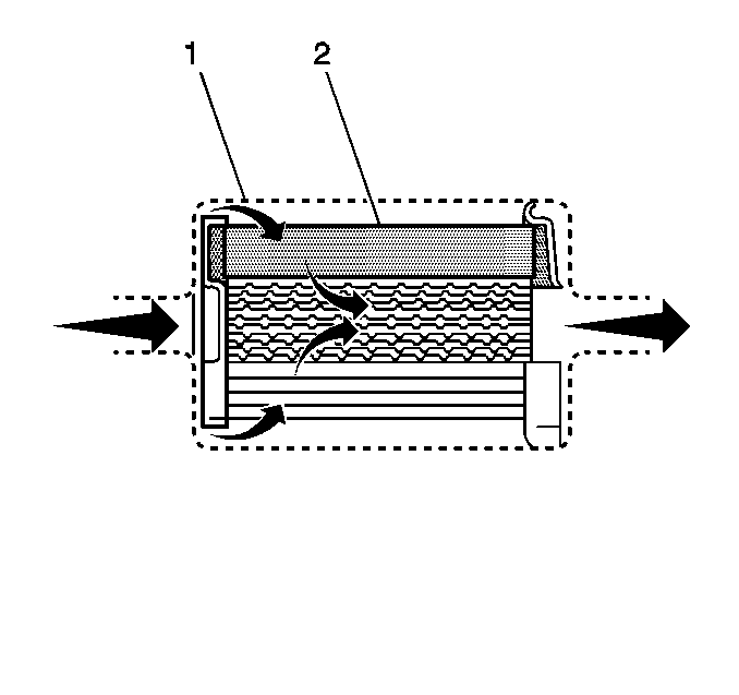
A fuel filter is used in the fuel feed pipe ahead of the fuel injection system. The fuel filter is mounted directly in front of the fuel tank. The fuel filter housing (1) is constructed of steel with a quick-connect fitting at the inlet of the fuel filter and a threaded fitting at the outlet of the fuel filter. The threaded fitting is sealed with an O-ring, which is replaceable. The filter element (2) is made of paper and is designed to trap particles suspended in the fuel that may damage the injection system.
There is no service interval for in-pipe fuel filter replacement. Only replace the in-pipe fuel filter if it is restricted.
Fuel Feed and Fuel Return Pipes
The fuel feed and fuel return pipes carry fuel from the fuel sender assembly to the fuel injection system and back to the fuel sender assembly.
Nylon Fuel Pipes
Caution: In order to Reduce the Risk of Fire and Personal Injury:
• If nylon fuel pipes are nicked, scratched or damaged during installation,
Do Not attempt to repair the sections of the nylon fuel pipes. Replace them. • When installing new fuel pipes, Do Not hammer directly on the
fuel harness body clips as it may damage the nylon pipes resulting in a possible
fuel leak. • Always cover nylon vapor pipes with a wet towel before using a
torch near them. Also, never expose the vehicle to temperatures higher than
115°C (239°F) for more than one hour, or more than 90°C (194°F)
for any extended period. • Before connecting fuel pipe fittings, always apply a few drops
of clean engine oil to the male pipe ends. This will ensure proper reconnection
and prevent a possible fuel leak. (During normal operation, the O-rings located
in the female connector will swell and may prevent proper reconnection if
not lubricated.)
Nylon fuel pipes are designed to perform the same job as the steel or rubber fuel lines they replace. Nylon pipes are constructed to withstand maximum fuel system pressure, exposure to fuel additives and changes in temperature. There are two sizes used: 3/8 inch ID for the fuel feed, and 5/16 inch ID for the fuel return and are used on the modular sender. Nylon fuel pipes are somewhat flexible and can be formed around gradual turns. However, if forced into sharp bends, nylon pipes will kink and restrict fuel flow. Also, once exposed to fuel, nylon pipes may become stiffer and are more likely to kink if bent too far. Special care should be taken when working on a vehicle with nylon pipes.
Quick Connect Fittings
Quick-connect type fittings provide a simplified means of installing and connecting fuel system components. Depending on the vehicle model, there are two types of quick-connect fittings, each used at different locations in the fuel system. Each type of quick-connect fitting consists of a unique female connector and a compatible male fuel pipe end. O-rings, located inside the female connector, provide the fuel seal. Integral locking tabs or fingers hold the quick-connect fittings together.
Fuel Pipe O-Rings
Fuel feed and return pipe threaded connections at the fuel rail and fuel filter are sealed with replaceable O-ring seals. These O-rings seals are made of special material, and should only be serviced with the correct service part.
Fuel Tank Pressure Sensor
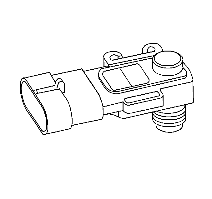
The fuel tank pressure sensor is a three wire strain gauge sensor much like that of the common GM MAP sensor. However, this sensor has very different electrical characteristics due to its pressure differential design. The sensor measures the difference between the air pressure (or vacuum) in the fuel tank and the outside air pressure. The sensor mounts at the top of the fuel tank. A three wire electrical harness connects it to the Powertrain Control Module (PCM). The PCM supplies a five volt reference voltage and ground to the sensor. The sensor will return a voltage between 0.1 and 4.9 volts. When the air pressure in the fuel tank is equal to the outside air pressure, such as when the fuel fill cap is removed, the output voltage of the sensor will be 1.3 to 1.7 volts. Refer to Information Sensors/Switches Description further information and diagnosis of the enhance EVAP system.
Enhanced Evaporative Emission (EVAP) Service Port
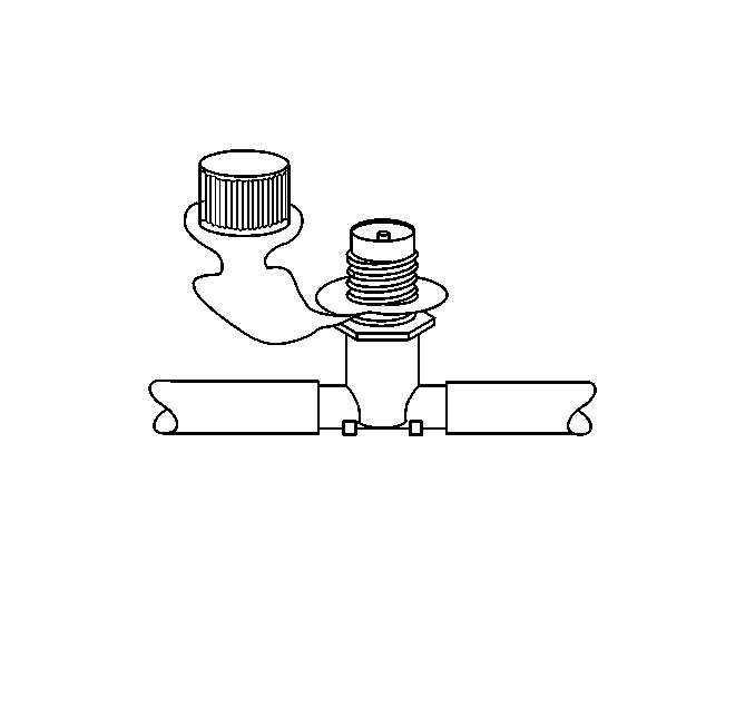
The enhanced EVAP service port is located in the evaporative purge hose located between the purge solenoid and the canister. The service port is identified by a green colored cap. The port contains a schrader valve and fittings to allow connections of J 41413 evaporative pressure/purge diagnostic system. Refer to Information Sensors/Switches Description for further information and diagnosis of the enhanced EVAP system.
