Circuit Description
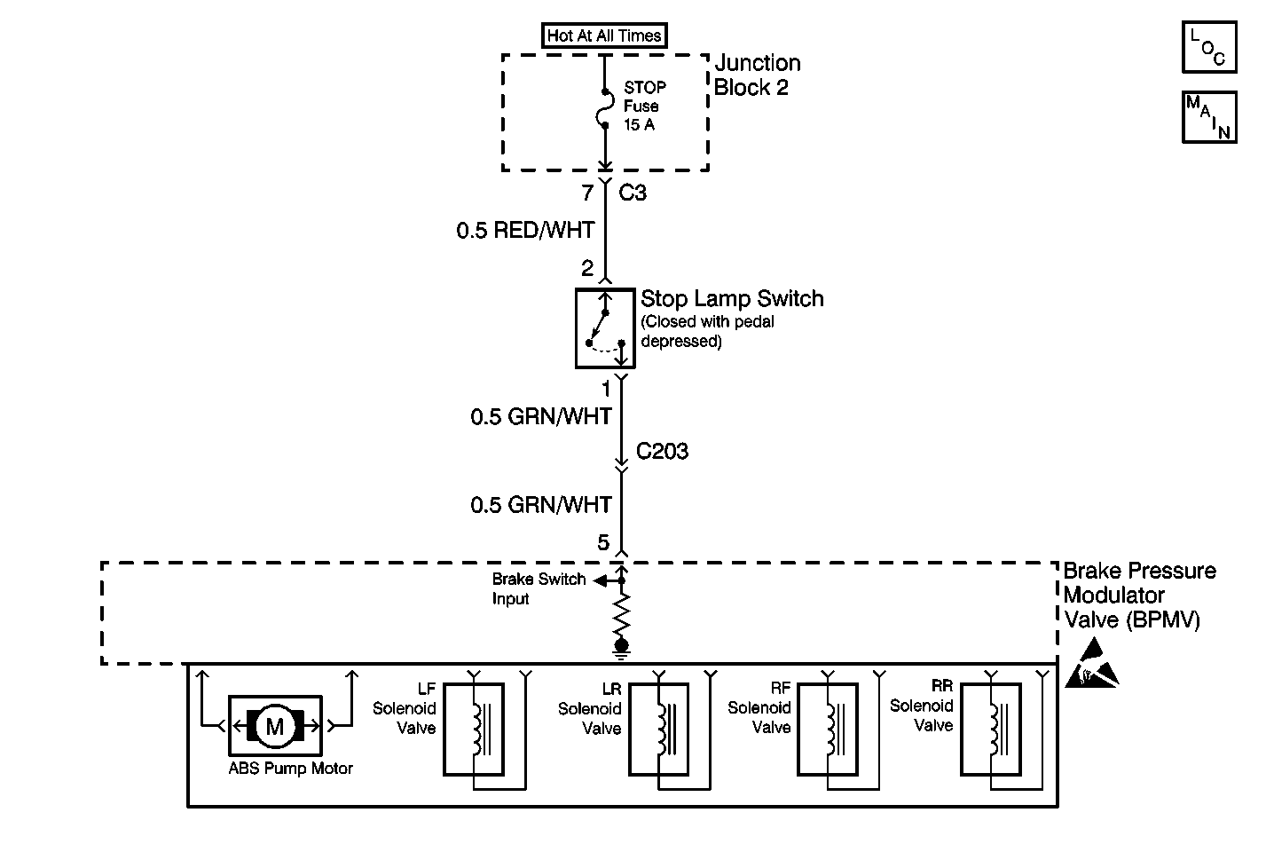
The Electronic Brake Control Module (EBCM) monitors brake pedal position through the stoplamp switch. The stoplamp switch is closed when the brake pedal is pressed and the stop lamp switch opens when the brake pedal is released. When the stoplamp switch is closed, the EBCM terminal 5 receives a voltage signal from the stoplamp switch electrical connector terminal 1. The stoplamp switch receives power from the STOP fuse.
Conditions for Setting the DTC
| • | DTC B3449 identifies an open in the stoplamp switch circuit. |
| • | DTC B3449 can be set anytime. |
Action Taken When the DTC Sets
The EBCM stores DTC B3449 turns ON the ABS indicator. If this DTC sets during the ABS stop, ABS will remain functional untill the vehicle stops. Otherwise ABS is disabled.
Conditions for Clearing the DTC
The condition for the malfunction is no longer present and command the Clear DTC Information function with a scan tool.
Diagnostic Aids
Inspect the following list of items when diagnosing this part of the Antilock Brake System (ABS):
| • | Open STOP Fuse (possible short to ground in its circuitry) |
| • | Stoplamp switch out of adjustment |
| • | Faulty stoplamp switch (contacts open or closed at the time) |
| • | Open circuit between the stoplamp switch and the EBCM |
| • | Short to voltage between the stoplamp switch and the EBCM |
An intermittent malfunction is most likely caused by following conditions:
| • | A poor connection |
| • | A rubbed through wire insulation |
| • | A wire that is broken inside the insulation |
Inspect the following harness connectors for the following conditions:
| • | Backed-out terminals |
| • | Improper mating |
| • | Broken locks |
| • | Improperly formed or damaged terminals |
| • | Poor terminal to wiring connections or physical damage to the wiring harness before component replacement: |
| - | Junction block electrical connectors |
| - | Stoplamp switch electrical connector |
| - | EBCM electrical connector |
Test Description
The number(s) below refer to the step number(s) on the diagnostic table.
-
Tests the stoplamp switch status of the Electronic Brake control Module (EBCM) through a scan tool.
-
Tests the tail lamps for proper operation.
-
Tests for a stoplamp switch that is out of adjustment or contacts closed all the time.
-
Tests the power distribution to the stoplamp switch.
-
Test for an open or a high resistance in the power circuit to the stoplamp switch.
-
Tests for a faulty stoplamp switch.
-
Tests for an open or a high resistance in the GRN/WHT circuit between the Stop Lamp Switch and the EBCM/BPMV assembly.
Step | Action | Value(s) | Yes | No |
|---|---|---|---|---|
1 | Was the Diagnostic System Check performed? | -- | Go to Step 2 | |
Does the scan tool display the stoplamp switch status ON with the brake pedal pressed and the stoplamp switch status OFF with the brake pedal released? | -- | Go to Step 17 | Go to Step 3 | |
With the help of an assistant, press then release brake pedal while observing the rear brake lamps. Did the brake lamps turn ON with the brake pedal pressed and the brake lamps turn OFF with the brake pedal released? | -- | Go to Step 8 | Go to Step 4 | |
Do the brake lamps stay ON at all times? | -- | Go to Step 9 | Go to Step 5 | |
Remove and inspect the STOP fuse. Is the STOP fuse open? | -- | Go to Step 10 | Go to Step 6 | |
Is the voltage within the specified range? | 0-1 v | Go to Step 11 | Go to Step 7 | |
Is the resistance within the specified range for both readings? | Brake Pedal Released: OL (Infinite) Brake Pedal Pressed: 0-2 ohms | Go to Step 12 | Go to Step 13 | |
Is the resistance within the range specified in the Value(s) column? | 0-2 ohms | Go to Step 14 | Go to Step 15 | |
9 | Disconnect the stoplamp switch electrical connector. Are the brake lamps OFF? | -- | Go to Step 13 | Go to Step 16 |
10 | Repair the short to ground in the stop lamp switch circuit between Junction Block 2 and the EBCM/BPMV assembly. Refer to Wiring Repairs in Wiring Systems. Is the repair complete? | -- | -- | |
11 | Repair the open in the RED/WHT wire between the STOP fuse and the stoplamp switch. Refer to Wiring Repairs in Wiring Systems. Is the repair complete? | -- | -- | |
12 |
Is the repair complete? | -- | -- | |
13 |
Is the repair complete? | -- | ||
14 |
Is the repair complete? | -- | -- | |
15 | Repair the open in the GRN/WHT wire between the stoplamp switch harness connector terminal 1 and the EBCM harness connector terminal 5. Refer to Wiring Repairs in Wiring Systems. Is the repair complete? | -- | -- | |
16 | Repair the short to voltage in the GRN/WHT wire. Refer to Wiring Repairs in Wiring Systems. Is the repair complete? | -- | -- | |
17 | A malfunction is not present at this time. Refer to Diagnostic Aids for additional information regarding this DTC. Is the action complete? | -- | -- |
