Circuit Description
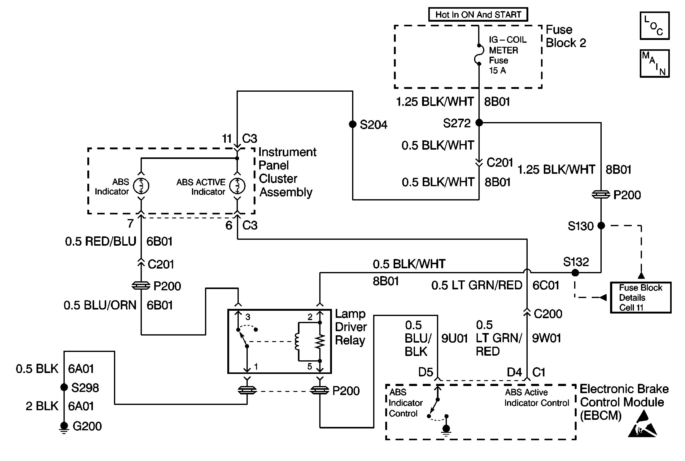
The EBCM controls the operation of the amber ABS indicator lamp by means of a lamp driver relay.
The amber ABS indicator lamp is connected to the IG-COIL METER fuse through CKT 8B01. This circuit is hot in ON and START ignition switch positions.
When the lamp driver relay is in the OFF state (CKT 9U01 is open), the lamp driver relay grounds the amber ABS indicator lamp through CKT 6B01. This causes the amber ABS warning indicator to turn ON.
When the EBCM commands the ABS indicator OFF, the EBCM turns ON the lamp driver relay by grounding CKT 9U01. This causes the lamp driver relay to open the path to ground in CKT 6B01, turning OFF the amber ABS indicator lamp.
When the ignition switch is turned to the ON position, the EBCM turns ON the ABS indicator for 3 seconds for a bulb check. Whenever a malfunction is detected within the ABS system, the EBCM turns ON the ABS indicator, notifying the driver that ABS needs to be serviced. If the EBCM commands the red BRAKE warning indicator ON due to an ABS malfunction that may degrade base braking operation and cannot do so, the ABS indicator will flash to indicate the serious nature of the problem.
Diagnostic Aids
The following conditions may cause an intermittent malfunction:
| • | A poor connection |
| • | Rubbed-through wire insulation |
| • | A broken wire inside the insulation |
Thoroughly inspect any circuitry that may cause the intermittent complaint for the following conditions:
| • | Backed out terminals |
| • | Improper mating |
| • | Broken locks |
| • | Improperly formed or damaged terminals |
| • | Poor terminal-to-wiring connections |
| • | Physical damage to the wiring harness |
| • | Open IG-COIL METER fuse |
| • | Open bulb filament |
| • | Open or poor G200 |
| • | Open or damage in the lamp driver relay control circuit (CKT 9U01) |
| • | Open within I/P gage printed circuit |
| • | Malfunctioning lamp driver relay (open contacts) |
Important: Zero the J 39200 test leads before making any resistance measurements. Refer to the J 39200 user's manual.
Step | Action | Value(s) | Yes | No | ||||||
|---|---|---|---|---|---|---|---|---|---|---|
1 | Was the Diagnostic System Check performed? | -- | Go to Diagnostic System Check | |||||||
2 |
Did the amber ABS warning indicator turn ON? | -- | ||||||||
3 |
Did the amber ABS Active warning indicator turn ON? | -- | ||||||||
4 |
Did the amber ABS warning indicator turn ON? | -- | ||||||||
5 | Connect the fused jumper wire between the relay harness connector terminal 3 and ground. Did the amber ABS warning indicator turn ON? | -- | ||||||||
6 | Repair the open or high resistance in CKT 6A01 or ground G200. Is the repair complete? | -- | Go to Diagnostic System Check | -- | ||||||
7 | Repair the open or high resistance in CKT 6B01. Is the repair complete? | -- | Go to Diagnostic System Check | -- | ||||||
8 |
Was an open found and repaired? | -- | Go to Diagnostic System Check | |||||||
9 | Use the J 39200 in order to measure the resistance between relay terminals 1 and 3. Is the resistance within the specified range? | 0-2 ohms | ||||||||
10 |
Is the resistance within the specified range? | OL (Infinite) | ||||||||
11 | Repair the short to ground in CKT 9U01. Is the repair complete? | -- | Go to Diagnostic System Check | -- | ||||||
12 | Replace the EBCM. Refer to Electronic Brake Control Module Replacement . Is the repair complete? | -- | Go to Diagnostic System Check | -- | ||||||
13 | Replace the Lamp Driver Relay. Refer to Lamp Driver Relay Replacement . Is the repair complete? | -- | Go to Diagnostic System Check | -- | ||||||
14 | The malfunction is not present at this time. Refer to Diagnostic Aids for more information. Is the action complete? | -- | Go to Diagnostic System Check | -- | ||||||
15 | Inspect the IG-METER Fuse. Is the fuse open? | -- | ||||||||
16 |
Is the voltage within the specified range? | Battery Voltage | ||||||||
17 | Repair the instrument panel cluster. Refer to Instrument Cluster, Cell 8I in Electrical Diagnosis. Is the repair complete? | -- | Go to Diagnostic System Check | -- | ||||||
18 | Repair the open or high resistance in CKT 8B01. Is the repair complete? | -- | Go to Diagnostic System Check | -- | ||||||
19 | Inspect the following components for a possible short:
Was a problem found and corrected? | -- | Go to Diagnostic System Check | -- |
