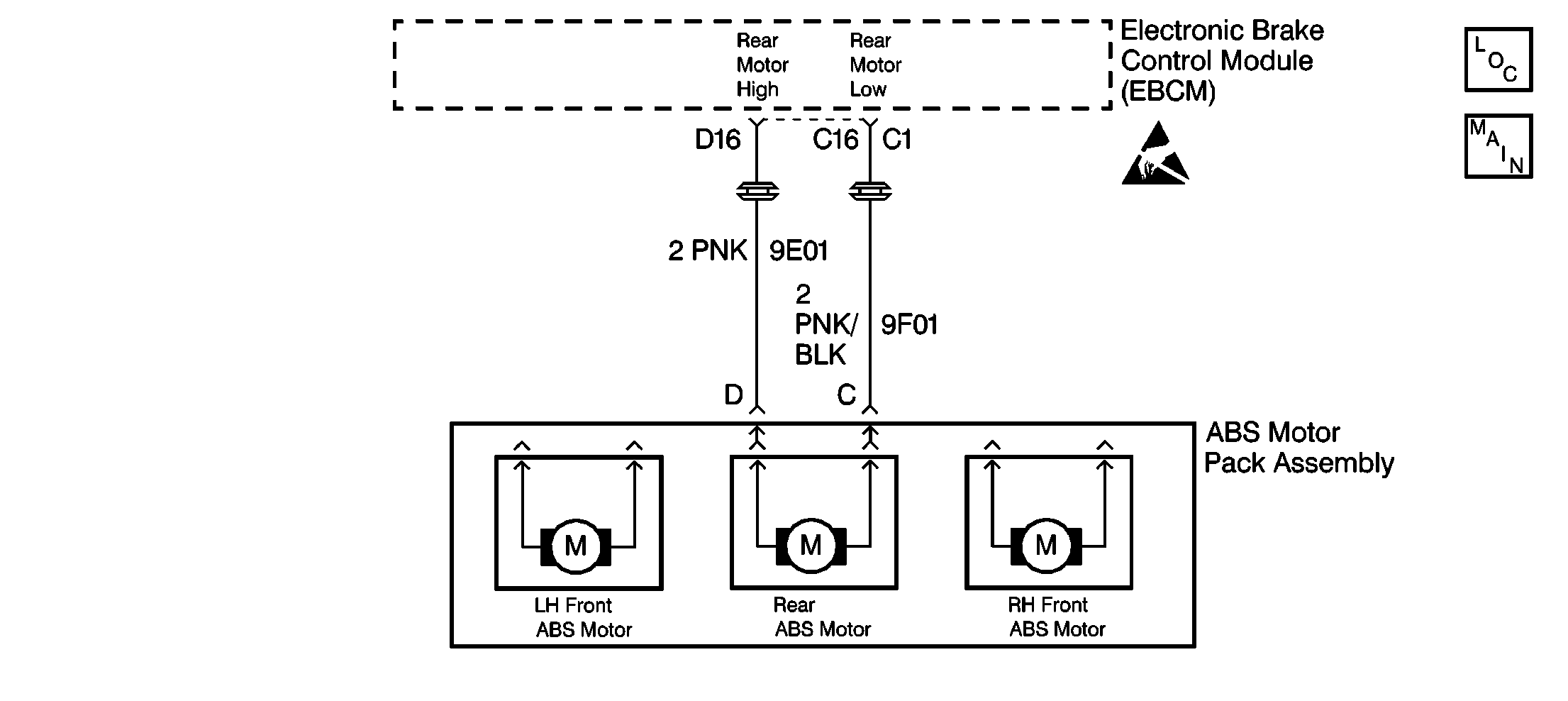
Circuit Description
DTC C1246 detects a bound-up ESB, a stuck ABS motor, or a seized brake modulator. When the release is commanded during initialization, the ESB should release the ABS motor, resulting in the feedback current being less than the commanded current (motor spins freely). If the ABS motor is not moving, feedback current will be equal to commanded current.
Conditions for Setting the DTC
DTC C1246 can set during brake motor initialization at the following speeds:
| • | 0 km/h (0 mph) when the brake is off |
| • | 5 km/h (3 mph) when the brake is on |
DTC C1246 can set during ABS stops
A malfunction exists if the EBCM detects a condition in which the EBCM cannot move the ABS motor in either direction.
Action Taken When the DTC Sets
| • | A malfunction DTC stores. |
| • | The ABS disables. |
| • | The ABS warning indicator turns ON. |
Conditions for Clearing the DTC
| • | The condition responsible for setting the DTC no longer exists and the Scan Tool Clear DTCs function is used. |
| • | 100 drive cycles pass with no DTCs detected. A drive cycle consists of starting the vehicle, driving the vehicle over 16 km/h (10 mph), stopping and then turning the ignition off. |
Diagnostic Aids
The following conditions may cause an intermittent malfunction if the conditions exist in a mechanical part of the system:
| • | Sticking |
| • | Binding |
Use the enhanced diagnostic function of the Scan Tool in order to measure the frequency of the malfunction. DTC C1246 may set after modulator disassembly if the modulator pistons are positioned at the bottom of the modulator piston bore. Depending on the frequency of the malfunction, a physical inspection of the mechanical parts suspected of causing the malfunction may be necessary.
Clear the DTCs after completing the diagnosis. Test drive the vehicle for three drive cycles in order to verify that the DTC does not reset. Use the following procedure in order to complete one drive cycle:
- Start the vehicle.
- Drive the vehicle over 16 km/h (10 mph).
- Stop the vehicle.
- Turn the ignition to the OFF position.
Important: Zero the J 39200 test leads before making any resistance measurements. Refer to the J 39200 user's manual.
Step | Action | Value(s) | Yes | No | ||||||||
|---|---|---|---|---|---|---|---|---|---|---|---|---|
1 | Was the Diagnostic System Check performed? | -- | Go to Diagnostic System Check | |||||||||
2 | Inspect the following connectors for the correct wire color/connector cavity combinations:
Are the correct wires located in the correct connector cavities? | -- | ||||||||||
3 |
Verify that the rear wheels are approximately 15 cm (six in) above the floor. Refer to Lifting and Jacking the Vehicle in General Information. Do not start the engine. Is it possible to rotate the rear wheels by hand? | -- | ||||||||||
4 |
Is it possible to rotate the rear wheels by hand? | -- | ||||||||||
5 |
Did the rear motor feedback current momentarily drop below the specified current? | 8 A | ||||||||||
6 |
Is the resistance within the specified range? | OL (Infinite) | ||||||||||
7 | Use the J 39200 in order to measure the resistance between the ABS brake motor pack connector terminal D and the ABS brake motor pack connector terminal C. Is the resistance within the specified range? | 0.2-1.5 ohms | ||||||||||
8 |
Do any of the terminals exhibit poor terminal contact or corrosion? | -- | ||||||||||
9 |
Does DTC C1246 set during the last three ignition cycles? | -- | ||||||||||
10 |
Is it possible to rotate the middle gear on the hydraulic modulator at least 4 1/2 revolutions from lock to lock? | -- | ||||||||||
11 | Place the wires into the correct connector cavities. Refer to Antilock Brakes System Connector End Views. Is the repair complete? | -- | Go to Diagnostic System Check | -- | ||||||||
12 | Repair the short between CKT 9E01 and CKT 9F01. Is the repair complete? | -- | Go to Diagnostic System Check | -- | ||||||||
13 | Replace the ABS motor pack. Refer to ABS Motor Pack Replacement . Is the repair complete? | -- | Go to Diagnostic System Check | -- | ||||||||
14 | Replace the hydraulic modulator. Is the repair complete? | -- | Go to Diagnostic System Check | -- | ||||||||
15 | Replace the terminals that exhibit signs of poor terminal contact or corrosion. Is the repair complete? | -- | Go to Diagnostic System Check | -- | ||||||||
16 | Replace the EBCM. Refer to Electronic Brake Control Module Replacement . Is the repair complete? | -- | Go to Diagnostic System Check | -- | ||||||||
17 | The malfunction is intermittent or is not present at this time. Refer to Diagnostic Aids for more information. Is the action complete? | -- | System OK | -- |
