Special Tools
| • | EN-48245 Camshaft Locking Tool |
| • | EN-48946 Crankshaft Locking Tool |
For equivalent regional tools, refer to Special Tools.
Removal Procedure
- Remove engine cover. Refer to Engine Cover Replacement.
- Remove air cleaner assembly. Refer to Air Cleaner Assembly Replacement.
- Raise vehicle by its full height. Refer to Lifting and Jacking the Vehicle.
- Remove the front compartment insulator. Refer to Front Compartment Insulator Replacement.
- Remove the generator and air conditioning compressor and power steering pump belt. Refer to Generator and Air Conditioning Compressor and Power Steering Pump Belt Replacement.
- Remove the drive belt tensioner. Refer to Drive Belt Tensioner Replacement.
- Remove the belt idler pulley. Refer to Belt Idler Pulley Replacement.
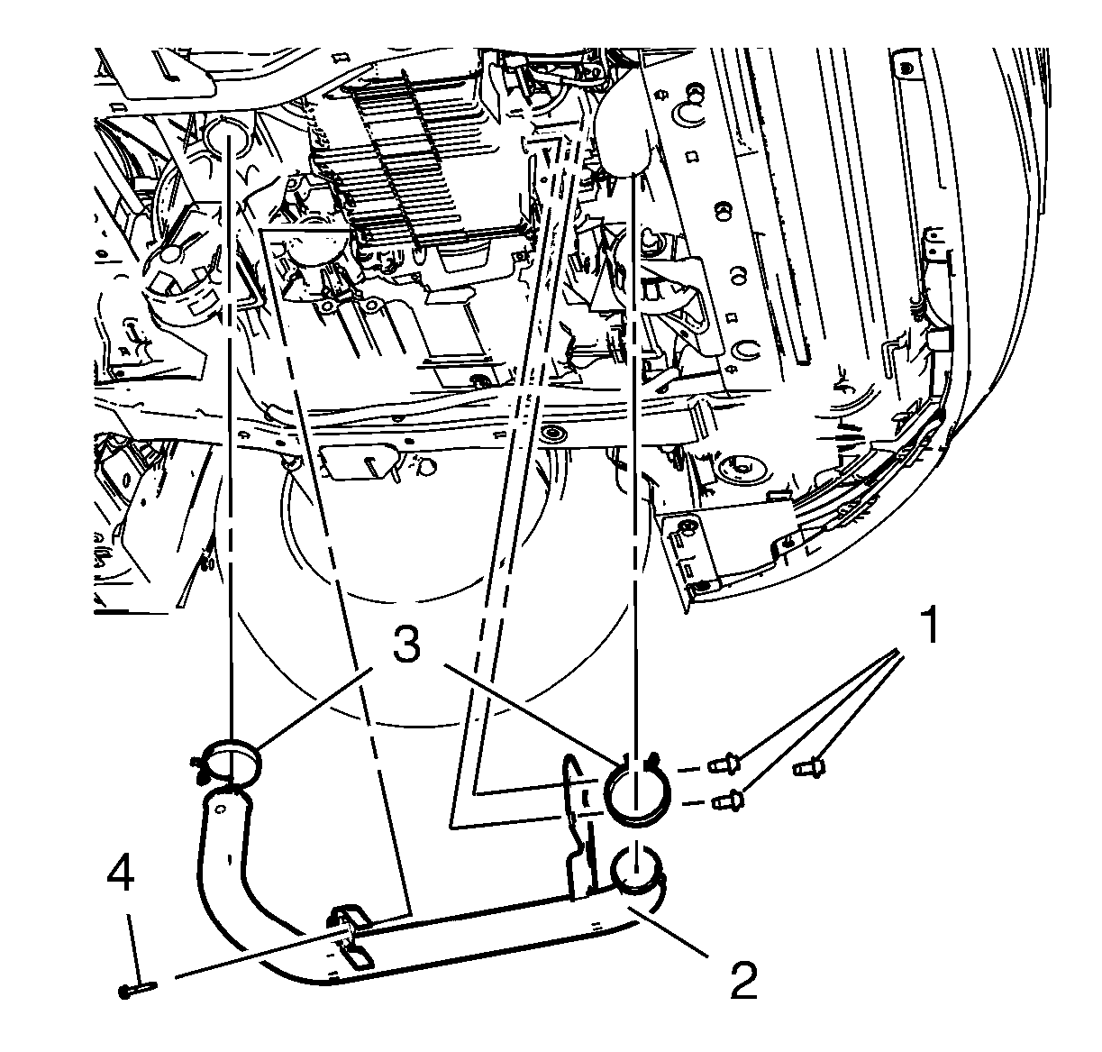
- Remove the charge air cooler inlet air tube bolt (4).
- Remove the 2 hose clamps (3).
- Remove the 3 air charge air cooler inlet air tube bolts (1).
- Remove the charge air cooler inlet air tube (2).
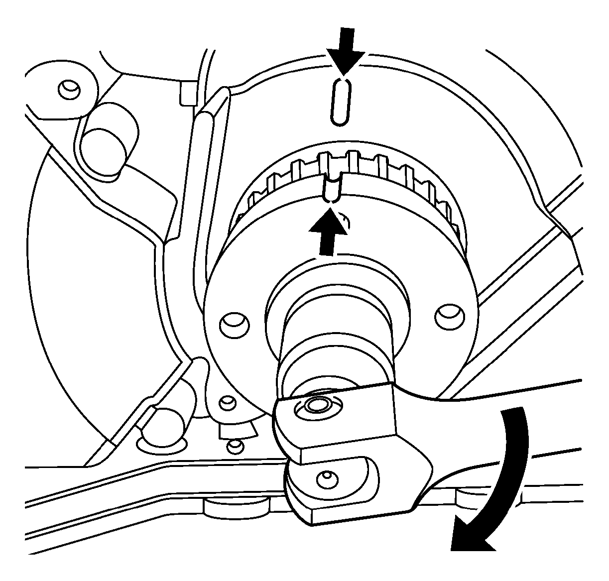
- Rotate the crankshaft to the markings at the crankshaft sprocket and oil pump cover.
- Remove the lower crankcase closure bolt (5).
- Install mounting engine/transmission. Refer to Engine/Transmission Mounting.
- Remove the generator and air conditioning compressor and power steering pump belt. Refer to Generator and Air Conditioning Compressor and Power Steering Pump Belt Replacement.
- Remove the drive belt tensioner. Refer to Drive Belt Tensioner Removal.
- Remove the belt idler pulley. Refer to Drive Belt Idler Pulley Removal.
- Remove the crankshaft idler pulley. Refer to Crankshaft Pulley Replacement.
- Remove timing belt lower front cover. Refer to Timing Belt Lower Front Cover Removal.
- Lower the vehicle full height.
- Remove the engine right mount. Refer to Engine Mount Replacement - Right Side.
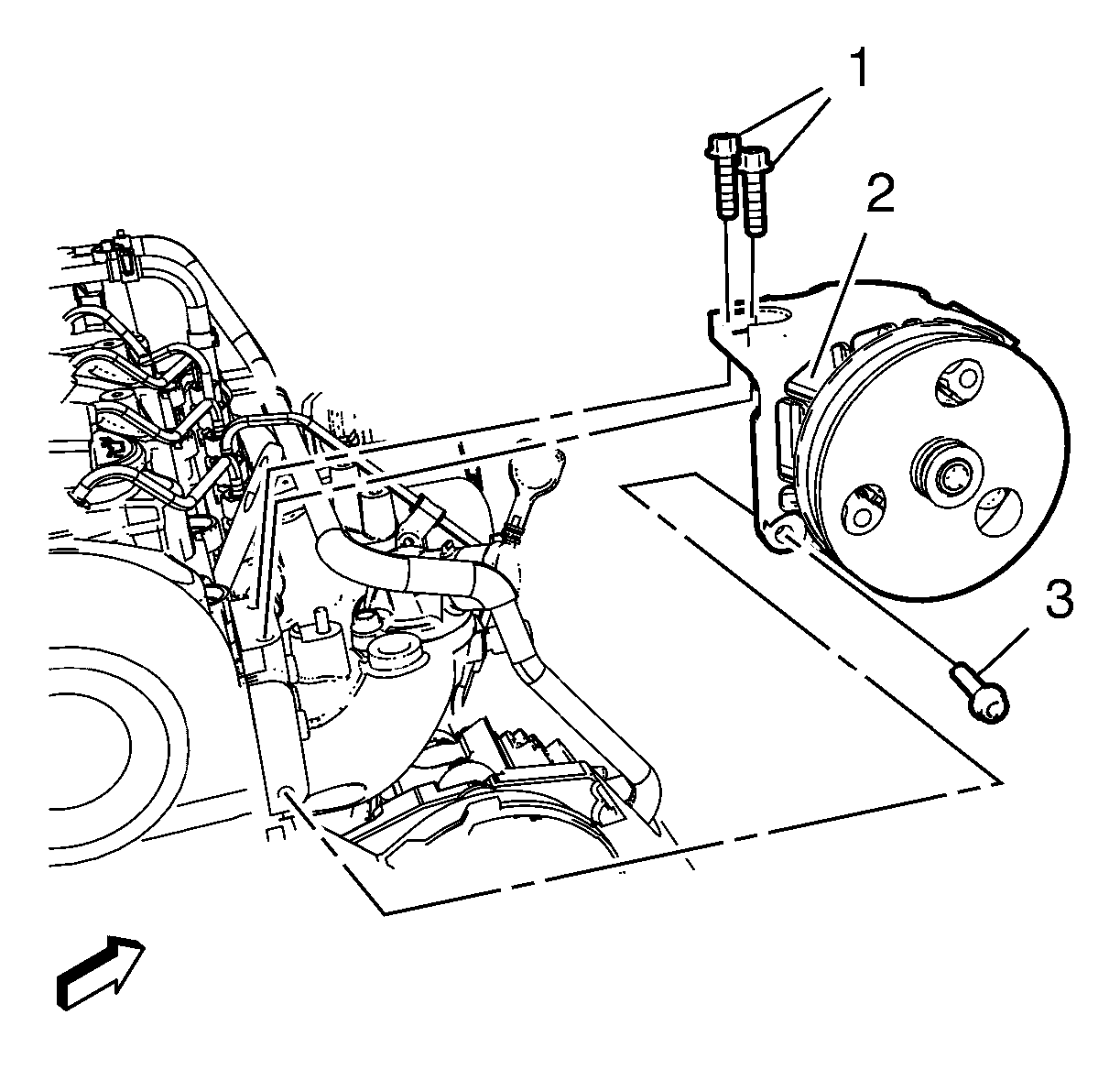
- Remove the steering pump bolts (1, 2).
- Remove the steering pump (2) out of the work area.
- Remove the timing belt upper front cover. Refer to Timing Belt Upper Front Cover Removal.
- Remove the vacuum pump. Refer to Vacuum Pump Removal.
- Rotate the camshaft (1) to the position as shown in the graphic.
- If the markings from crankshaft and camshaft not align remove the EN-48245 locking tool turn the crankshaft 360° and install EN-48245 locking tool . Refer to step 11.
- Install the EN-48946 locking tool (1) to fix the camshaft and install the 4 bolts (2) and tighten to 12 N·m (107 ft in).
- Loosen the timing belt tensioner bolt (2).
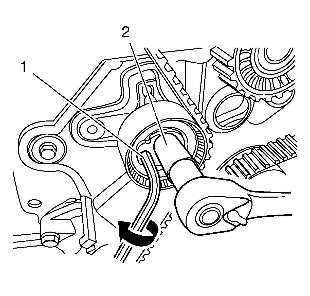
- Turn the timing belt tensioner with an hex-key (1) clockwise until the timing belt is solved.
- Remove the timing belt (1).
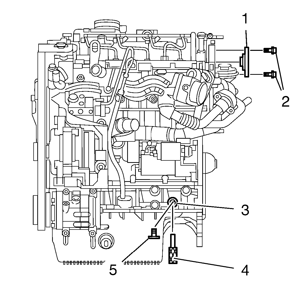
Install EN-48245 locking tool (4) into the lower crankcase hole (3). Turn the crankshaft until the tool engages into the crankshaft.
185
Note: Do not disconnect the power steering hoses.
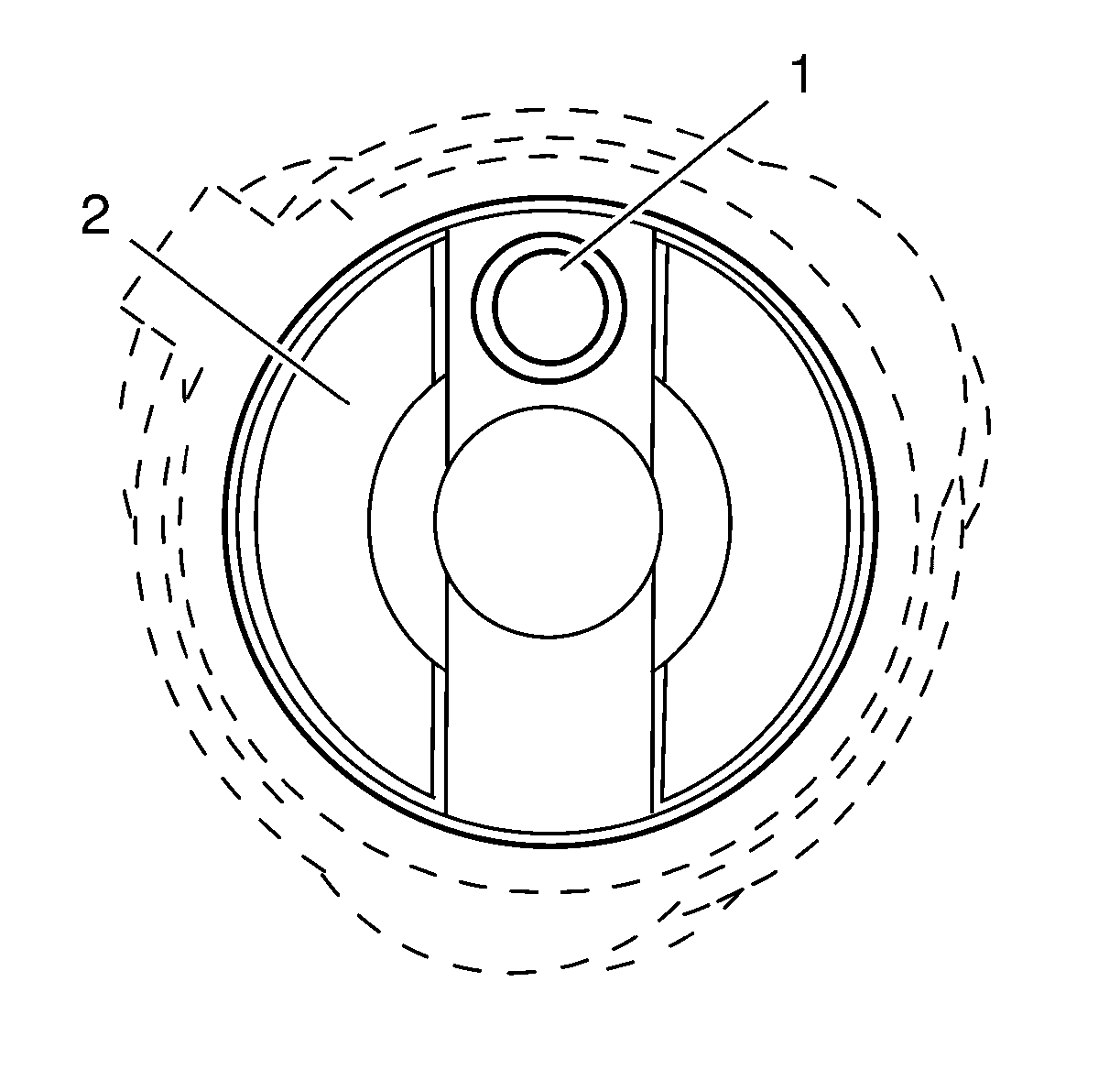
Note:
• Examine that the bore (1) inside the camshaft (2) is on top. • Examine the correct positions of the camshaft and the crankshaft.

Installation Procedure
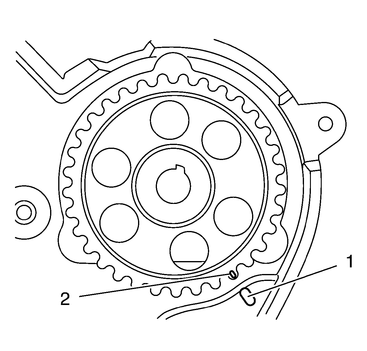
- Rotate the fuel pump drive sprocket that the marks (1) and (2) align.
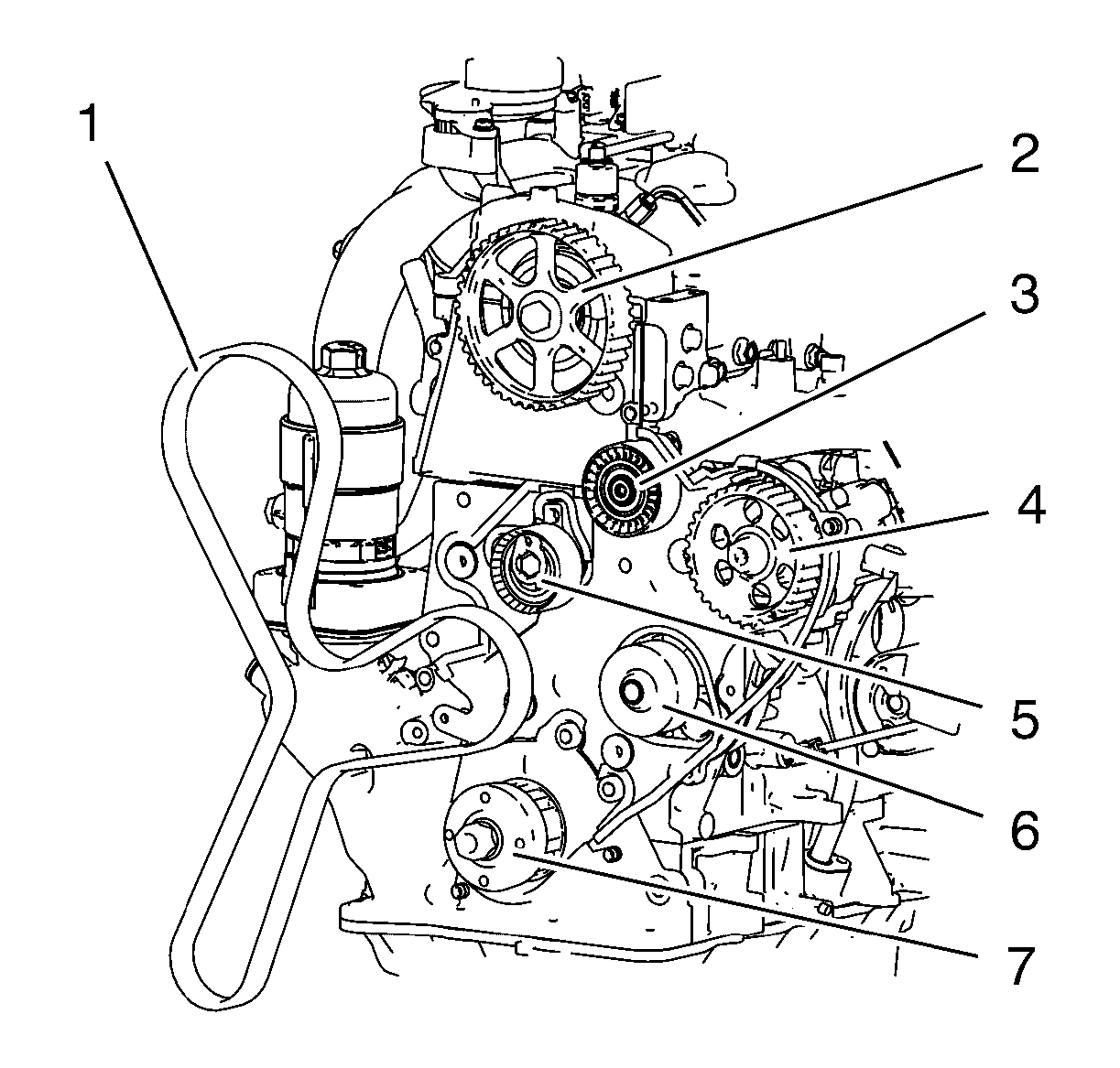
- Install the Timing Belt (1) in the following order:
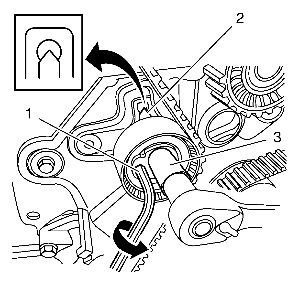
- Turn the hex-key (1) tab in a counterclockwise direction to tension the belt. Turn until the point aligns with the notch (2).
- Aligning with (2) notch, tighten the timing belt tensioner bolt (3) to 25 N·m (19 lb ft).
- Remove the EN-48946 locking tool (1) and remove the bolts (2).
- Raise vehicle by its full height.
- Remove EN-48245 locking tool (4) from the lower crankcase hole (3). Install the lower crankcase closure bolt (5) and tighten to 30 N·m (23 lb ft).
- Turn the crankshaft in a clockwise direction 2 cycles and check the positions from the crankshaft.
- Lower the vehicle full height.
- Check the camshaft position.
- Install the timing belt upper front cover. Refer to Timing Belt Upper Front Cover Installation.
- Install the vacuum pump. Refer to Vacuum Pump Installation.
- Install the engine right mount. Refer to Engine Mount Replacement - Right Side.
- Install the steering pump (2).
- Install the steering pump bolts (1, 2) and tighten to 22 N·m (16 lb ft).
- Raise the vehicle by its full height.
- Install the timing belt lower front cover. Refer to Timing Belt Lower Front Cover Installation.
- Install the crankshaft idler pulley. Refer to Crankshaft Pulley Installation.
- Install the drive belt tensioner. Refer to Drive Belt Tensioner Installation.
- Install the belt idler pulley. Refer to Belt Idler Pulley Installation.
- Install the generator and air conditioning compressor and power steering pump belt. Refer to Generator and Air Conditioning Compressor and Power Steering Pump Belt Replacement.
- Remove mounting engine/transmission. Refer to Engine/Transmission Mounting.
- Install the charge air cooler inlet air tube (2).
- Install the 3 charge air cooler inlet air tube bolts (1) and tighten to .
- Install the 2 hose clamps (3).
- Install the charge air cooler inlet air tube bolt (4) and tighten to 10 N·m (89 lb in).
- Install the belt idler pulley. Refer to Belt Idler Pulley Replacement.
- Install the drive belt tensioner. Refer to Drive Belt Tensioner Replacement.
- Install the generator and air conditioning compressor and power steering pump belt. Refer to Generator and Air Conditioning Compressor and Power Steering Pump Belt Replacement.
- Install the front compartment insulator. Refer to Front Compartment Insulator Replacement.
- Lower the vehicle full height.
- Install air cleaner assembly. Refer to Air Cleaner Assembly Replacement.
- Install engine cover. Refer to Engine Cover Replacement.

Note: Examine the correct traveling direction of the timing belt.
Note: Examine that the timing belt is tensioned during the installation.
| 2.1. | Crankshaft sprocket (7) |
| 2.2. | Water pump pulley (6) |
| 2.3. | Fuel pump drive pulley (4) |
| 2.4. | Timing belt idler pulley (3) |
| 2.5. | Camshaft drive sprocket (2) |
| 2.6. | Timing belt tensioner (5) |
Caution: Refer to Fastener Caution in the Preface section.


Note: If the timing marks are not aligned, repeat the forward procedure and recheck the marks. Alignment of marks is important for engine performance and emissions.

Note:
• Examine that the bore (1) in the camshaft (2) is on top. • Examine the correct positions of the camshaft and the crankshaft.


