Caution: Avoid breathing the A/C Refrigerant 134a (R-134a) and the lubricant
vapor or the mist. Exposure may irritate the eyes, nose, and throat. Work
in a well ventilated area. In order to remove R-134a from the A/C system,
use service equipment that is certified to meet the requirements of SAE J
2210 (R-134a recycling equipment). If an accidental system discharge occurs,
ventilate the work area before continuing service. Additional health and safety
information may be obtained from the refrigerant and lubricant manufacturers.
Caution: Do not operate the detector in a combustible atmosphere since its sensor
operates at high temperatures or personal injury and/or damage to the equipment
may result.
Perform a refrigerant leak test on the system when the
following conditions exist:
| • | A service operation disturbs the components, lines or connections. |
Electronic Leak Detector
Tools Required
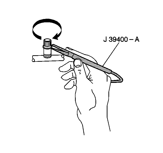
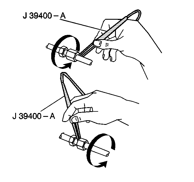
J 39400 Electronic
Leak Detector

The J 39400
is a small unit which operates on
12V DC.
The detector provides an audible signal. The signal increases in frequency
as R-134a is detected.
Use the included instructions in order to ensure that the instrument
is properly calibrated. Ensure that the detector is used in the proper setting
for the type of refrigerant being tested.
Place the detector GAS switch in the R-134a setting prior to use.
Inspect the refrigerant fittings and the connections for leaks. The
following conditions may cause leaks:
| • | Lack of lubricant on the O-ring seals |
| • | Dirt or debris across the O-ring seals |
| • | Small pieces of lint from cotton gloves or shop cloths |

When using the electronic leak detector, ensure that the following conditions
exist:
| • | Each joint is completely circled. |
| • | The scan rate is 25-51 mm (1.2 in) per second. |
| • | The tip of the probe is as close to the surface as possible but
no more than 6 mm (0.25 in) away. |
| • | The air intake is not blocked. |
Important: Halogen leak detectors are sensitive to the following compounds:
| • | Windshield washing solutions |
A leak is indicated when the audible tone changes from a steady 1-2
clicks per second to a solid alarm. Adjust the balance knob frequently in
order to maintain the 1-2 clicks per second rate.
Important: Always follow the refrigerant system around in a continuous path so
that no areas of potential leaks are missed. Always test all of the following
areas in order to ensure that the entire system is leak free,
even when one leak is already found.
Use this procedure in order to test the following areas:
| • | The Evaporator inlet and outlet |
| • | The accumulator inlet and outlet |
| • | The condenser inlet and outlet |
| • | All brazed and welding areas |
| • | All areas that exhibit signs of damage |
| • | The Compressor rear head |
Service Ports/Access Valves
The sealing gap is the primary seal for the service ports. This cap
contains a specially designed O-ring seal or gasket which provides a leak-free
seal.
The following conditions will result in the loss of refrigerant charge:
Evaporator Core
Leaks in the Evaporator core may be difficult to detect. Use the following
procedure in order to test the core:
- Turn the blower fan on HIGH for 15 or more seconds.
- Turn off the blower fan.
- Wait for 10 minutes.
- Remove the blower motor resistor. Refer to
Blower Motor Resistor Replacement
in Heating and
Ventilation.
- Insert the leak detector probe. Be sure to insert the leak detector
as close to the Evaporator as possible.
- Listen to the detector. If the detector sounds a solid alarm,
a leak has been found.
- Visually inspect the core face with a flashlight for evidence
of refrigerant oil.
Compressor Block Fittings and Shaft Seal
- Blow shop air behind and in front of the Compressor clutch/pulley
for 15 seconds or more.
- Wait for 1-2 minutes.
- Probe the area in front of the pulley.
- Listen to the detector. If the detector sounds a solid alarm,
a leak has been found.


