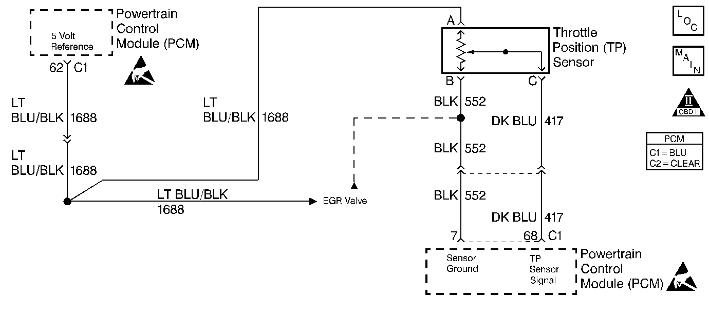
Circuit Description
The Throttle Position sensor is potentiometer. A 5 volt reference is provided on CKT 1688 and ground is provided on CKT 552. The TP sensor signal CKT 417 varies between ground and 5 volts based on the position of the throttle plates. At low throttle angle, the TP sensor signal voltage is low. The PCM uses TP sensor information to determine idle, Wide Open Throttle (WOT), deceleration enleanment and acceleration enrichment. This diagnostic test is designed to determine when the throttle position sensor reading is too high out of its estimated range for its current operating engine speed. The PCM does this by monitoring changes in TP sensor within a certain period of time. If the change is 0.6 degrees or less within 0.1 second, the PCM compares the current throttle position with a stored throttle position that is considered acceptable for the current engine speed. If the current throttle position is greater than the stored value the TP sensor is considered stuck and DTC P0121 will set.
Conditions for Running the DTC
| • | DTCs P0106, P0107, P0108, P0122, and P0123 not set. |
| • | Engine speed 400 RPM or greater. |
| • | Throttle position changes less than 0.6 degrees in 0.1 second. |
| • | Manifold absolute pressure is less than or equal to 60.3 kPa. |
| • | Traction control not active. |
| • | All 8 cylinders are enabled. |
| • | Engine overheat not present. |
Conditions for Setting the DTC
The throttle position sensor input is not within its expected range.
Action Taken When the DTC Sets
PCM disables the torque converter clutch.
| • | The PCM will illuminate the Malfunction Indicator Lamp (MIL) when the diagnostic runs and fails. |
| • | The PCM will record operating conditions at the time the diagnostic fails. This information will be stored in the Freeze Frame and Failure Records. |
Conditions for Clearing the MIL/DTC
| • | The PCM will turn the MIL OFF after three consecutive drive trips that the diagnostic runs and does not fail. |
| • | A Last Test Failed (current) DTC will clear when the diagnostic runs and does not fail. |
| • | A History DTC will clear after forty consecutive warm-up cycles with no failures of any emission related diagnostic test. |
| • | Use a scan tool to clear DTCs. |
| • | Interrupting PCM battery voltage may or may not clear DTCs. This practice is not recommended. Refer to Clearing Diagnostic Trouble Codes in Powertrain Control Module Description . |
Test Description
The numbers below refer to the step numbers on the Diagnostic Table.
Step | Action | Value(s) | Yes | No |
|---|---|---|---|---|
1 | Did you perform the Powertrain On-Board Diagnostic (OBD) System Check? | -- | Go to Step 2 | |
2 |
Is the TP sensor reading greater than the value specified? | .01 volts | Go to Step 3 | Go to DTC P0122 Throttle Position (TP) Sensor Circuit Low Voltage |
Was a stuck condition observed? | -- | Go to Step 4 | Go to P0106 diagnosis. | |
4 | Replace the Throttle Position sensor. Refer to Throttle Position Sensor Replacement . Is the replacement complete? | -- | Go to Powertrain Control Module Diagnosis for Verify Repair | -- |
