Removal Procedure
Tools Required
| • | J 28467-A Engine Support Fixture |
| • | J 38416-B Crankshaft Balancer Remover |
| • | J 41998-A Crankshaft Balancer Installer |
| • | J 39411 Flywheel Holder |
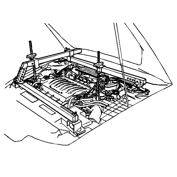
- Install the J 28467-A .
- Remove the accessory drive belt from the crankshaft balancer (5).
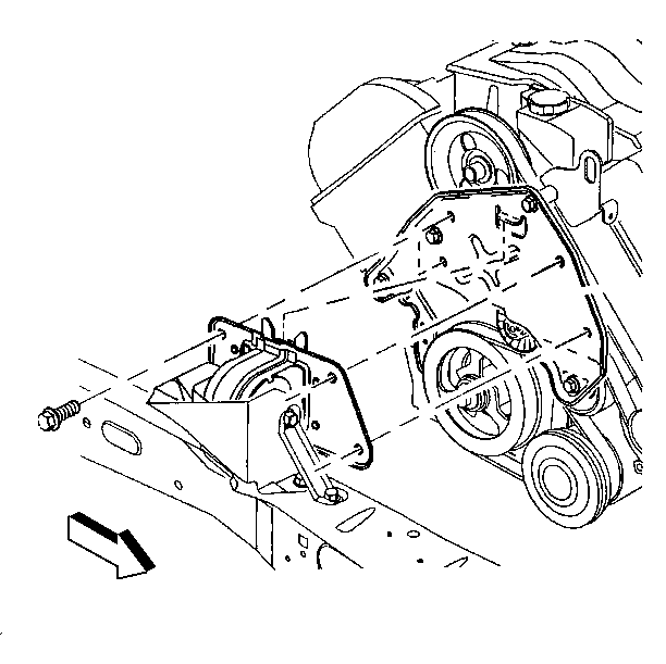
- Remove the torque axis engine mount/bracket assembly. Refer to Engine Mount Replacement .
- Lower the engine using the support fixture to obtain the clearance for the J 38416-B below the body rail.
- Raise and support the vehicle. Refer to Lifting and Jacking the Vehicle in General Information.
- Remove the brace between the engine oil pan and transmission case.
- Secure the flywheel in order to prevent crankshaft rotation. Use the J 39411 .
- Remove the crankshaft balancer bolt.
- Place the J 41998-A in the end of the crankshaft.
- Position the ends of the legs of the J 38416-B onto the backside of the balancer inner hub.
- Tighten the center screw on the puller until the balancer pulls clear of the crankshaft end.
- Remove the crankshaft balancer.


Installation Procedure
Tools Required
| • | J 28467-A Engine Support Fixture |
| • | J 41998-A Crankshaft Balancer Installer |
| • | J 39411 Flywheel Holder |
- Position the crankshaft balancer on the nose of the crankshaft.
- Install the balancer using the J 41998-A .
- Clean the balancer bolt threads.
- Apply engine oil to the balancer bolt threads.
- Install the balancer bolt.
- Use the balancer legs as a reference for the additional 120 degrees of rotation. Make a mark on the balancer bolt flange in line with the centerline of one balancer spoke. Turn to the next spoke.
- Remove the flywheel holder.
- Install the oil pan to transaxle brace.
- Lower the vehicle.
- Raise the engine at the J 28467-A .
- Install the torque axis engine mount/bracket assembly. Refer to Engine Mount Replacement .
- Install the drive belt. Refer to Drive Belt Replacement .

Notice: Use the correct fastener in the correct location. Replacement fasteners must be the correct part number for that application. Fasteners requiring replacement or fasteners requiring the use of thread locking compound or sealant are identified in the service procedure. Do not use paints, lubricants, or corrosion inhibitors on fasteners or fastener joint surfaces unless specified. These coatings affect fastener torque and joint clamping force and may damage the fastener. Use the correct tightening sequence and specifications when installing fasteners in order to avoid damage to parts and systems.
Tighten
Tighten the crankshaft balancer bolt to 50 N·m + 120 degrees
(37 lb ft + 120 degrees).

Tighten
Tighten the four oil pan to transaxle brace bolts to 50 N·m
(37 lb ft).
