Brake Pressure Modulator Valve Replacement Buick with TCS
Removal Procedure
- Remove the air cleaner assembly. Refer to Air Cleaner Assembly Replacement in Engine Controls - 3.8L.
- Disconnect the negative battery cable.
- Disconnect the following electrical connectors from the BPMV:
- Remove the clamp that is on the reservoir hose to BPMV reservoir.
- Obtain a 15.5 mm (5/8 in) plug to be used in the next step.
- Disconnect the reservoir hose from the BPMV reservoir.
- Remove the primary brake pipe from the BPMV.
- Remove the secondary brake pipe from the BPMV.
- Remove the brake pipes from the BPMV.
- Remove the harness strap.
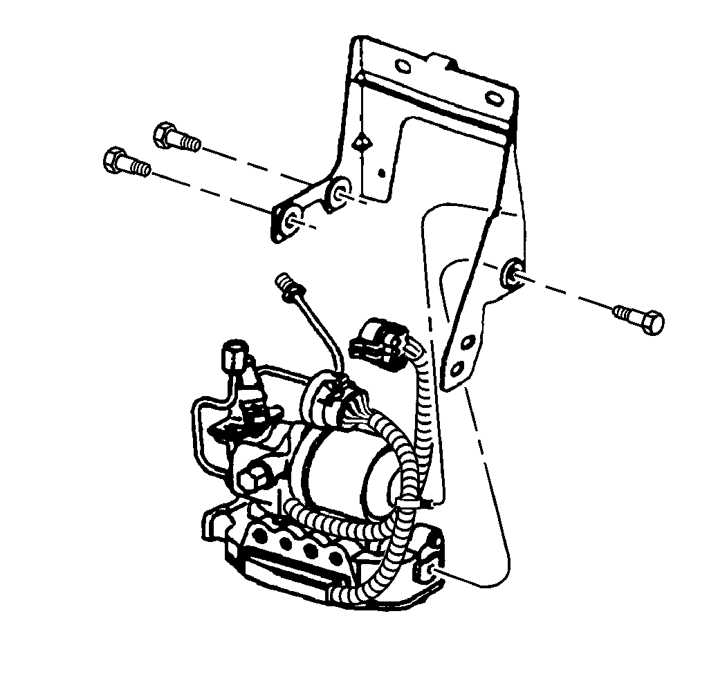
- Remove the BPMV bolts.
- Remove the BPMV.
- Transfer the necessary parts to the new BPMV unit. Refer to Brake Pressure Module Valve Reservoir Replacement , Brake Pressure Modulator Valve Bracket Replacement and Fastener Tightening Specifications .

Caution: For safety reasons, the brake pressure modulator valve assembly must not be repaired, the complete unit must be replaced. With the exception of the EBCM, no screws on the brake pressure modulator valve assembly may be loosened. If screws are loosened, it will not be possible to get the brake circuits leak-tight and personal injury may result.
Notice: The use of rubber hoses or parts other than those specified for the ABS may lead to functional problems requiring major overhaul.
Caution: Unless directed otherwise, the ignition and start switch must be in the OFF or LOCK position, and all electrical loads must be OFF before servicing any electrical component. Disconnect the negative battery cable to prevent an electrical spark should a tool or equipment come in contact with an exposed electrical terminal. Failure to follow these precautions may result in personal injury and/or damage to the vehicle or its components.
| • | The fluid level switch connector |
| • | The pump motor connector |
| • | The valve block connector |

Installation Procedure
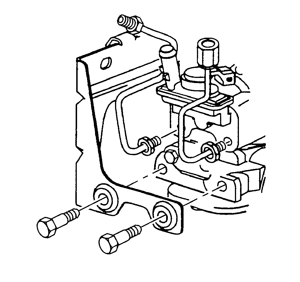
- Install the valve block to pump bolts.
- Install the BPMV.
- Install the BPMV mounting bolts.
- Install the harness strap.
- Install the brake pipes to the BPMV.
- Install the primary brake pipes to the BPMV.
- Install the secondary brake pipes to the BPMV.
- Connect the reservoir hose to the BPMV reservoir.
- Install the reservoir clamp.
- Install the following electrical connectors to the BPMV:
- Connect the negative battery cable.
- Install the air cleaner assembly. Refer to Air Cleaner Assembly Replacement in Engine Controls - 3.8L.
- Fill the brake fluid reservoir. Refer to Master Cylinder Reservoir Filling in Hydraulic Brakes.
- Bleed the brake system. Refer to Hydraulic Brake System Bleeding in Hydraulic Brakes.
- Clean the brake fluid from the BPMV area in order to prevent damage to vehicle components.
- Perform the ABS Diagnostic System Check. Refer to Diagnostic System Check - ABS .

Important: Improper installation or inversion of the metal gasket may introduce extremely high pressures during the autobleed procedure. This high pressure may cause severe damage to various components on the brake system.
Ensure that the locator tab position is correct so that none of the internal ports between the pump and the valve block assembly are blocked.Notice: Use the correct fastener in the correct location. Replacement fasteners must be the correct part number for that application. Fasteners requiring replacement or fasteners requiring the use of thread locking compound or sealant are identified in the service procedure. Do not use paints, lubricants, or corrosion inhibitors on fasteners or fastener joint surfaces unless specified. These coatings affect fastener torque and joint clamping force and may damage the fastener. Use the correct tightening sequence and specifications when installing fasteners in order to avoid damage to parts and systems.
Tighten
Tighten the valve block to pump bolts to 29 N·m (21.4 lb ft).
Tighten
Tighten the bolts to 27 N·m (20 lb ft).

Tighten
Tighten the brake pipes to 15 N·m (11 lb ft).
Tighten
Tighten the brake pipes to 15 N·m (11 lb ft).
| • | The fluid level switch connector |
| • | The pump motor connector |
| • | The valve block connector |
Tighten
Tighten the battery cable to 15 N·m (11 lb ft).
Brake Pressure Modulator Valve Replacement Buick without TCS
Removal Procedure
- Remove the air cleaner assembly. Refer to Air Cleaner Assembly Replacement in Engine Controls - 3.8L.
- Disconnect the negative battery cable.
- Disconnect the following electrical connectors from the BPMV:
- Remove the clamp that is on the reservoir hose to BPMV reservoir.
- Obtain a 15.5 mm (5/8 in) plug to be used in the next step.
- Remove the reservoir hose from the BPMV reservoir.
- Remove the primary brake pipe from the BPMV.
- Remove the secondary brake pipe from the BPMV.
- Remove the brake pipes from the BPMV.
- Remove the harness strap.
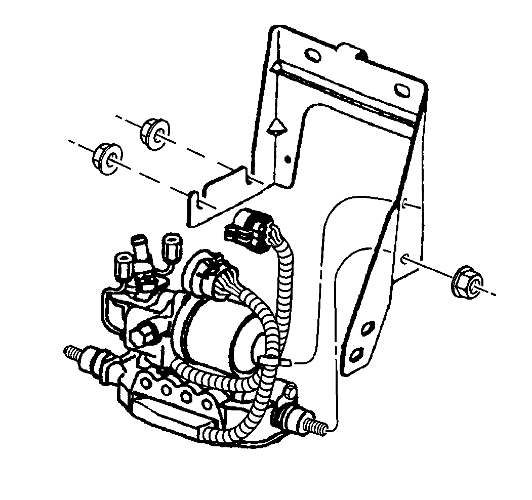
- Remove the BPMV mounting nuts.
- Remove the BPMV.
- Transfer the necessary parts to the new BPMV unit. Refer to Brake Pressure Module Valve Reservoir Replacement , Brake Pressure Modulator Valve Bracket Replacement and Fastener Tightening Specifications .

Caution: For safety reasons, the brake pressure modulator valve assembly must not be repaired, the complete unit must be replaced. With the exception of the EBCM, no screws on the brake pressure modulator valve assembly may be loosened. If screws are loosened, it will not be possible to get the brake circuits leak-tight and personal injury may result.
Notice: The use of rubber hoses or parts other than those specified for the ABS may lead to functional problems requiring major overhaul.
Caution: Unless directed otherwise, the ignition and start switch must be in the OFF or LOCK position, and all electrical loads must be OFF before servicing any electrical component. Disconnect the negative battery cable to prevent an electrical spark should a tool or equipment come in contact with an exposed electrical terminal. Failure to follow these precautions may result in personal injury and/or damage to the vehicle or its components.
| • | The fluid level switch connector |
| • | The pump motor connector |
| • | The valve block connector |

Installation Procedure
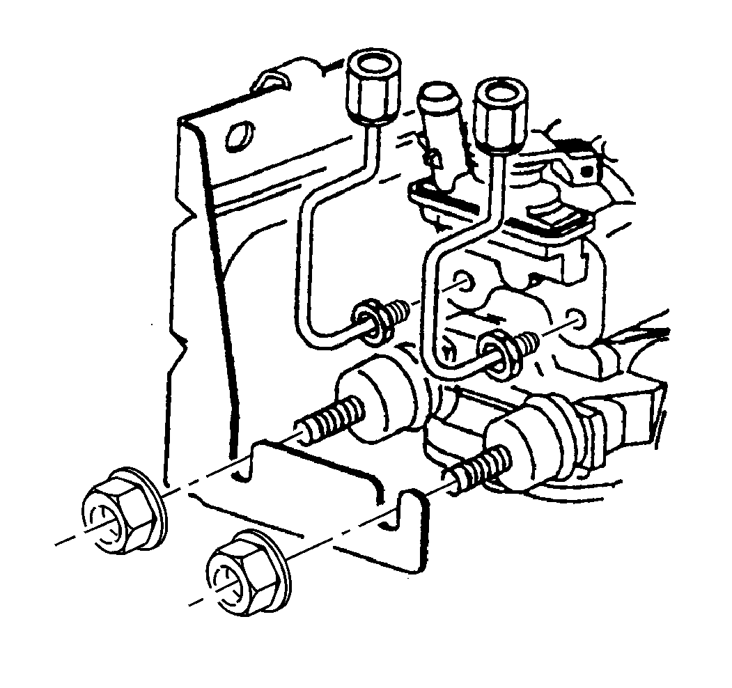
- Install the valve block to pump bolts.
- Install the BPMV.
- Install the BPMV mounting nuts.
- Install the harness strap.
- Install the brake pipes to the BPMV.
- Install the primary brake pipes to the BPMV.
- Install the secondary brake pipe to the BPMV.
- Connect the reservoir hose to the BPMV reservoir.
- Install the reservoir clamp.
- Install the following electrical connectors to the BPMV:
- Connect the negative battery cable.
- Install the air cleaner assembly. Refer to Air Cleaner Assembly Replacement in Engine Controls - 3.8L.
- Fill the brake fluid reservoir. Refer to Master Cylinder Reservoir Filling in Hydraulic Brakes.
- Bleed the brake system. Refer to Hydraulic Brake System Bleeding in Hydraulic Brakes.
- Clean the brake fluid from the BPMV area in order to prevent damage to the vehicle components.
- Perform the ABS Diagnostic System Check. Refer to Diagnostic System Check - ABS .

Important: Improper installation or inversion of the metal gasket may introduce extremely high pressures during the autobleed procedure. This high pressure may cause severe damage to various components on the brake system.
Ensure that the locator tab position is correct so that none of the internal ports between the pump and the valve block assembly are blocked.Notice: Use the correct fastener in the correct location. Replacement fasteners must be the correct part number for that application. Fasteners requiring replacement or fasteners requiring the use of thread locking compound or sealant are identified in the service procedure. Do not use paints, lubricants, or corrosion inhibitors on fasteners or fastener joint surfaces unless specified. These coatings affect fastener torque and joint clamping force and may damage the fastener. Use the correct tightening sequence and specifications when installing fasteners in order to avoid damage to parts and systems.
Tighten
Tighten the BPMV valve block to pump bolts to 29 N·m (21.4 lb ft).
Tighten
Tighten the nuts to 20 N·m (15 lb ft).

Tighten
Tighten the brake pipes to 15 N·m (11 lb ft).
Tighten
Tighten the brake pipes to 15 N·m (11 lb ft).
| • | The fluid level switch connector |
| • | The pump motor connector |
| • | The valve block connector |
Tighten
Tighten the battery cable to 15 N·m (11 lb ft).
Brake Pressure Modulator Valve Replacement Oldsmobile
Removal Procedure
- Disconnect the negative battery cable.
- Remove the air cleaner assembly. Refer to Air Cleaner Assembly Replacement in Engine Controls - 4.0.
- Disconnect the following electrical connectors from the BPMV:
- Remove the clamp that is on the reservoir hose to BPMV reservoir.
- Obtain a 15.5 mm (5/8 in) plug to be used in the next step.
- Remove the reservoir hose from the BPMV reservoir.
- Remove the primary brake pipe from the BPMV.
- Remove the secondary brake pipe from the BPMV.
- Raise and suitably support the vehicle. Refer to Lifting and Jacking the Vehicle in General Information.
- Remove the left front wheel splash shield. Refer to Wheelhouse Panel Replacement in Body Front End.
- Remove the brake pipes from the BPMV.
- Remove the BPMV to bracket bolts.
- Remove the BPMV from the bracket. Set the BPMV aside.
- Remove the BPMV bracket.
- Remove the BPMV from the vehicle through the left front wheel well.
- Transfer the necessary parts to the new BPMV unit. Refer to Brake Pressure Module Valve Reservoir Replacement , Brake Pressure Modulator Valve Bracket Replacement and Fastener Tightening Specifications .

Caution: For safety reasons, the brake pressure modulator valve assembly must not be repaired, the complete unit must be replaced. With the exception of the EBCM, no screws on the brake pressure modulator valve assembly may be loosened. If screws are loosened, it will not be possible to get the brake circuits leak-tight and personal injury may result.
Notice: The use of rubber hoses or parts other than those specified for the ABS may lead to functional problems requiring major overhaul.
Caution: Unless directed otherwise, the ignition and start switch must be in the OFF or LOCK position, and all electrical loads must be OFF before servicing any electrical component. Disconnect the negative battery cable to prevent an electrical spark should a tool or equipment come in contact with an exposed electrical terminal. Failure to follow these precautions may result in personal injury and/or damage to the vehicle or its components.
| • | The fluid level switch connector |
| • | The pump motor connector |
| • | The valve block connector |

Installation Procedure
- Install the BPMV valve block to pump bolts.
- Install the BPMV into the vehicle.
- Set the BPMV to the side.
- Install the BPMV bracket.
- Install the BPMV to bracket bolts.
- Install the brake pipes to the BPMV.
- Install the primary brake pipes to the BPMV.
- Install the secondary brake pipes to the BPMV.
- Connect the reservoir hose to the BPMV reservoir.
- Install the reservoir clamp.
- Install the following electrical connectors to the BPMV:
- Connect the negative battery cable.
- Install the left front splash shield. Refer to Wheelhouse Panel Replacement in Body Front End.
- Install the air cleaner assembly. Refer to Air Cleaner Assembly Replacement in Engine Controls - 4.0L.
- Fill the brake fluid reservoir. Refer to Master Cylinder Reservoir Filling in Hydraulic Brakes.
- Bleed the brake system. Refer to Hydraulic Brake System Bleeding in Hydraulic Brakes.
- Clean the brake fluid from the BPMV area in order to prevent damage to the vehicle components.
- Perform the ABS Diagnostic System Check. Refer to Diagnostic System Check - ABS .

Important: Improper installation or inversion of the metal gasket may introduce extremely high pressures during the autobleed procedure. This high pressure may cause severe damage to various components on the brake system.
Ensure that the locator tab position is correct so that none of the internal ports between the pump and the valve block assembly are blocked.Notice: Use the correct fastener in the correct location. Replacement fasteners must be the correct part number for that application. Fasteners requiring replacement or fasteners requiring the use of thread locking compound or sealant are identified in the service procedure. Do not use paints, lubricants, or corrosion inhibitors on fasteners or fastener joint surfaces unless specified. These coatings affect fastener torque and joint clamping force and may damage the fastener. Use the correct tightening sequence and specifications when installing fasteners in order to avoid damage to parts and systems.
Tighten
Tighten the BPMV valve block to pump bolts to 29 N·m (21.4 lb ft).
Tighten
Tighten the bolts to 27 N·m (20 lb ft).

Tighten
Tighten the brake pipes to 15 N·m (11 lb ft).
Tighten
Tighten the brake pipes to 15 N·m (11 lb ft).
| • | The fluid level switch connector |
| • | The pump motor connector |
| • | The valve block connector |
Tighten
Tighten the battery cable to 15 N·m (11 lb ft).
Testing BPMV for Internal Leaks
If internal leakage of the brake system is a reoccurring problem, perform the following test first in order to verify if the BPMV is malfunctioning or not.
- Remove the low pressure return hose at the BPMV reservoir.
- With the ignition switch in the RUN position, have an assistant gently apply pressure to the brake pedal three to five times.
- Inspect the BPMV reservoir outlet for fluid leaking out when pressure is applied to the brake system. If fluid leaks from the BPMV outlet, the BPMV is malfunctioning and should be replaced.
