Removal Procedure
Tools Required
| • | J 34730-1A Fuel Pressure Gauge |
| • | J 37088-A Fuel Line Quick-Connect Tools |
| • | J 41081 Injector Remover |
- Relieve the fuel system pressure. Refer to the Fuel Pressure Relief .
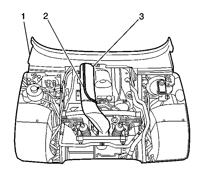
- Remove the engine dress cover (2).
- Remove the upper plastic wiper cowl (1).
- Remove the center plastic wiper cowl.
- Remove the air intake duct (3).
- Remove the intake manifold. Refer to Engine Mechanical.
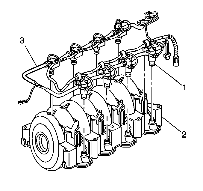
- Remove the fuel pressure regulator (1) from the fuel rail. Refer to the Fuel Pressure Regulator Replacement .
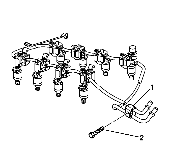
- Remove the fuel rail end-point bracket retainer bolt.
- Remove the throttle body mount bolts.
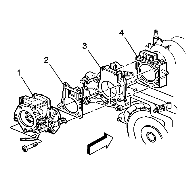
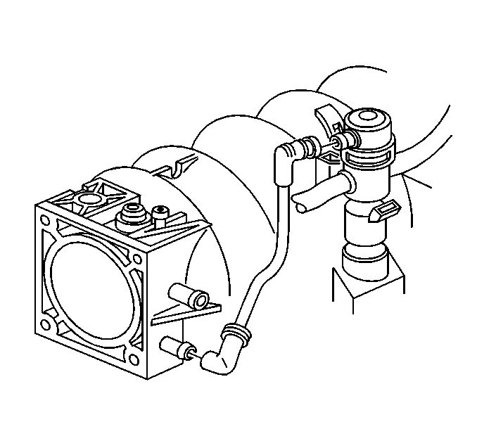
- Remove the throttle body. Refer to Throttle Body Assembly Replacement .
- Remove the throttle body spacer (3).
- Remove the intake manifold to the throttle body spacer O-ring seal.
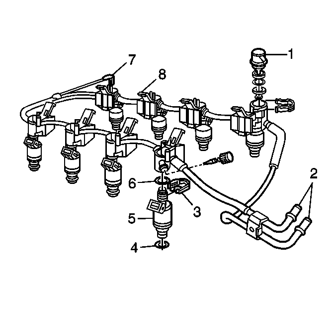
- Release the locking tabs (8) on the fuel rail by pushing toward the center of the intake manifold. Pry each injector out of the intake manifold using the J 41081 injector remover.
- Lift the fuel rail and move the fuel rail until the fuel pipes clear the intake plenum.
- An 8-digit identification number is stamped on the fuel rail assembly. The model identification number contains the julian date, the year, and the shift. Refer to this model identification number if servicing or part replacement is required.
Notice:
• Remove the fuel rail assembly carefully in order to prevent damage
to the injector electrical connector terminals and the injector spray tips.
Support the fuel rail after the fuel rail is removed in order to avoid damaging
the fuel rail components. • Cap the fittings and plug the holes when servicing the fuel system
in order to prevent dirt and other contaminants from entering open pipes and
passages.



Disassembly Procedure
- Remove the fuel injector harness.
- Remove the clips (3) from the injectors (5) on the fuel rail.
- Remove the upper (3) and lower (2) seals from the injectors (1).
- Discard the seals after removal.


Assembly Procedure
- Lubricate the upper (6) and lower (4) injector O-rings with clean oil and install the O-rings on to the fuel injectors.
- Assemble the injectors to the fuel rail with new retainer clips.
- Assemble the injector harness.


Installation Procedure
- Install the fuel rail with injectors to intake manifold.
- The fuel injectors are fully seated when a snap is heard.
- Install the new O-ring seal between the throttle body spacer (3) and the intake manifold (4).
- Install throttle body spacer (3).
- Install the new throttle body gasket (2) between the throttle body (1) and the throttle body spacer (3).
- Install the throttle body (1). Refer to Throttle Body Assembly Replacement .
- Install the throttle body mount bolts.
- Install the fuel pressure regulator if the fuel pressure regulator was removed from the fuel rail. Refer to Fuel Pressure Regulator Replacement .
- Install the intake manifold (2) to the engine. Refer to Engine Mechanical.
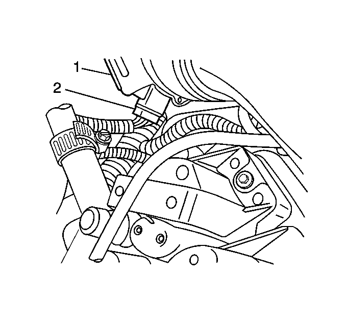
- Install the MAF sensor electrical connector (2) to the MAF sensor (1).
- Install the fuel rail end-point bracket (1) retainer bolt (2).
- Install the air intake duct (3).
- Tighten the fuel filler cap.
- Install the negative battery cable.
- Install the center plastic wiper arm cowl.
- Install the upper plastic wiper arm cowl (1).
- Install the engine dress cover (2).


Notice: Use the correct fastener in the correct location. Replacement fasteners must be the correct part number for that application. Fasteners requiring replacement or fasteners requiring the use of thread locking compound or sealant are identified in the service procedure. Do not use paints, lubricants, or corrosion inhibitors on fasteners or fastener joint surfaces unless specified. These coatings affect fastener torque and joint clamping force and may damage the fastener. Use the correct tightening sequence and specifications when installing fasteners in order to avoid damage to parts and systems.
Tighten
Tighten the throttle body spacer bolts to 12 N·m (106 lb in).
Tighten
Tighten the throttle body mount bolts to 12 N·m (106 lb in).

Tighten
Tighten the bolt to 11 N·m (97 lb in).

| 14.1. | Turn ignition ON for 2 seconds. |
| 14.2. | Turn the ignition OFF for 10 seconds. |
| 14.3. | Turn the ignition ON. |
| 14.4. | Inspect for fuel leaks. |
