For 1990-2009 cars only
| Figure 1: |
Power, Ground and MIL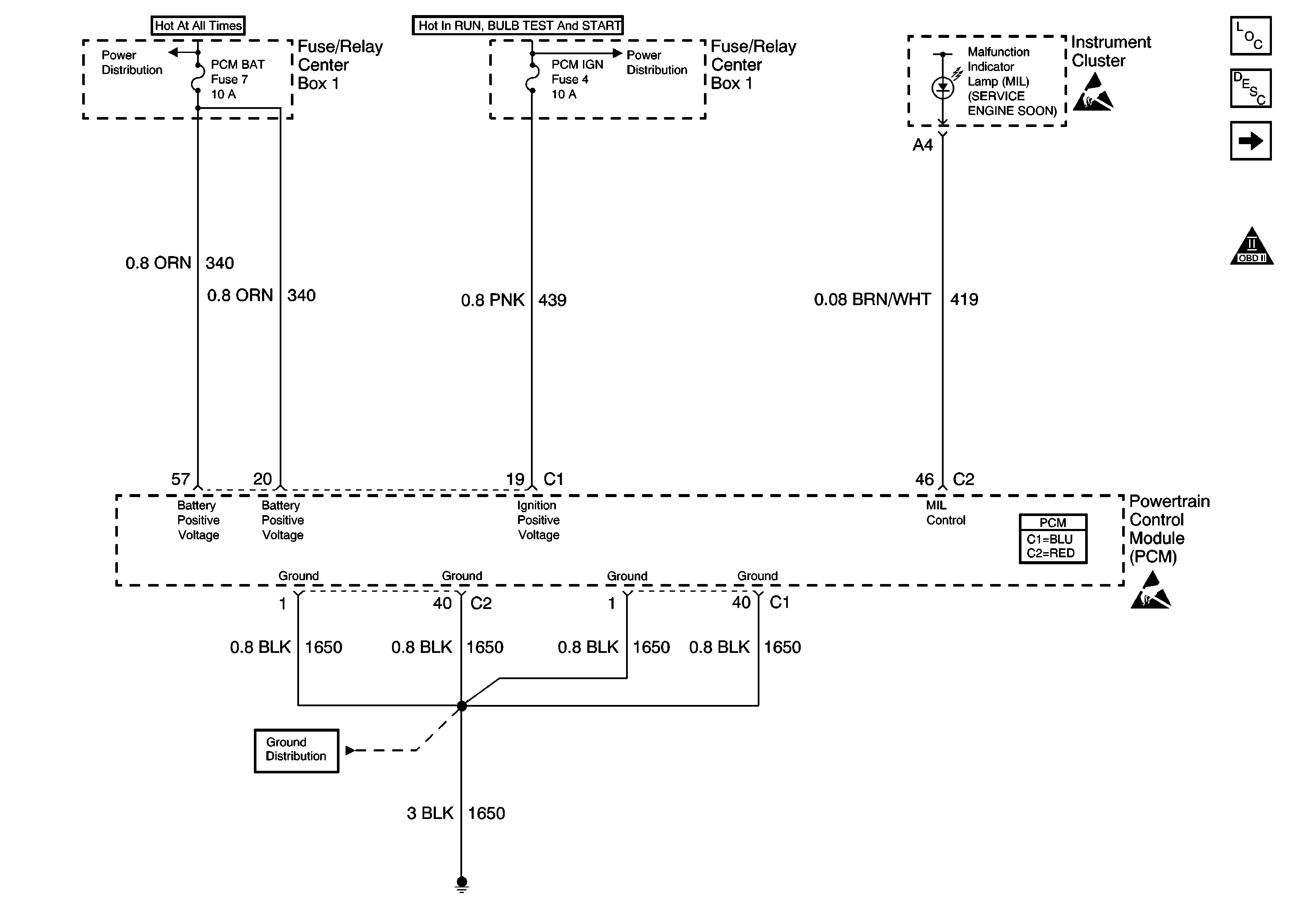
|
| Figure 2: |
Data Link Connector (DLC)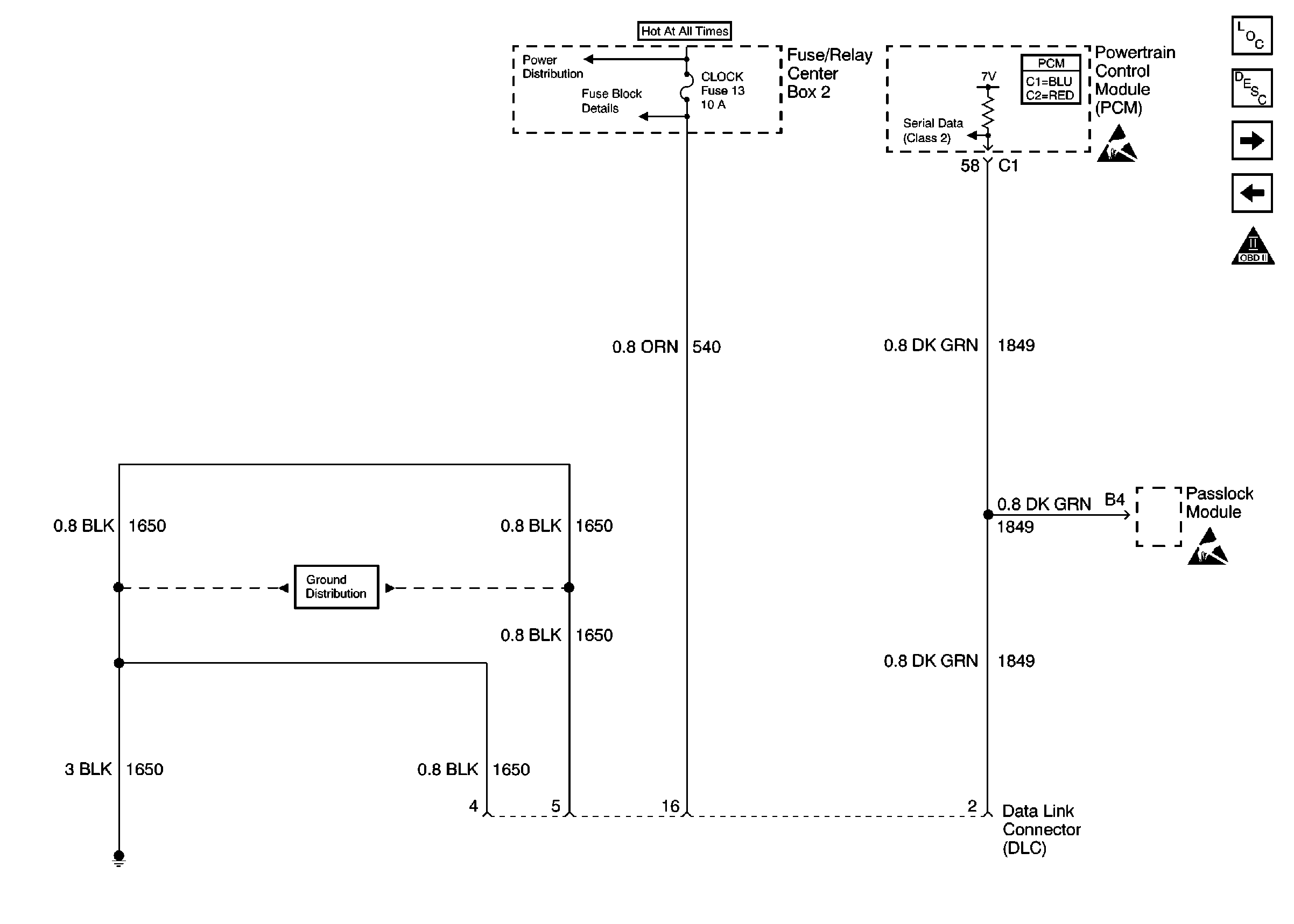
|
| Figure 3: |
Ignition Control Module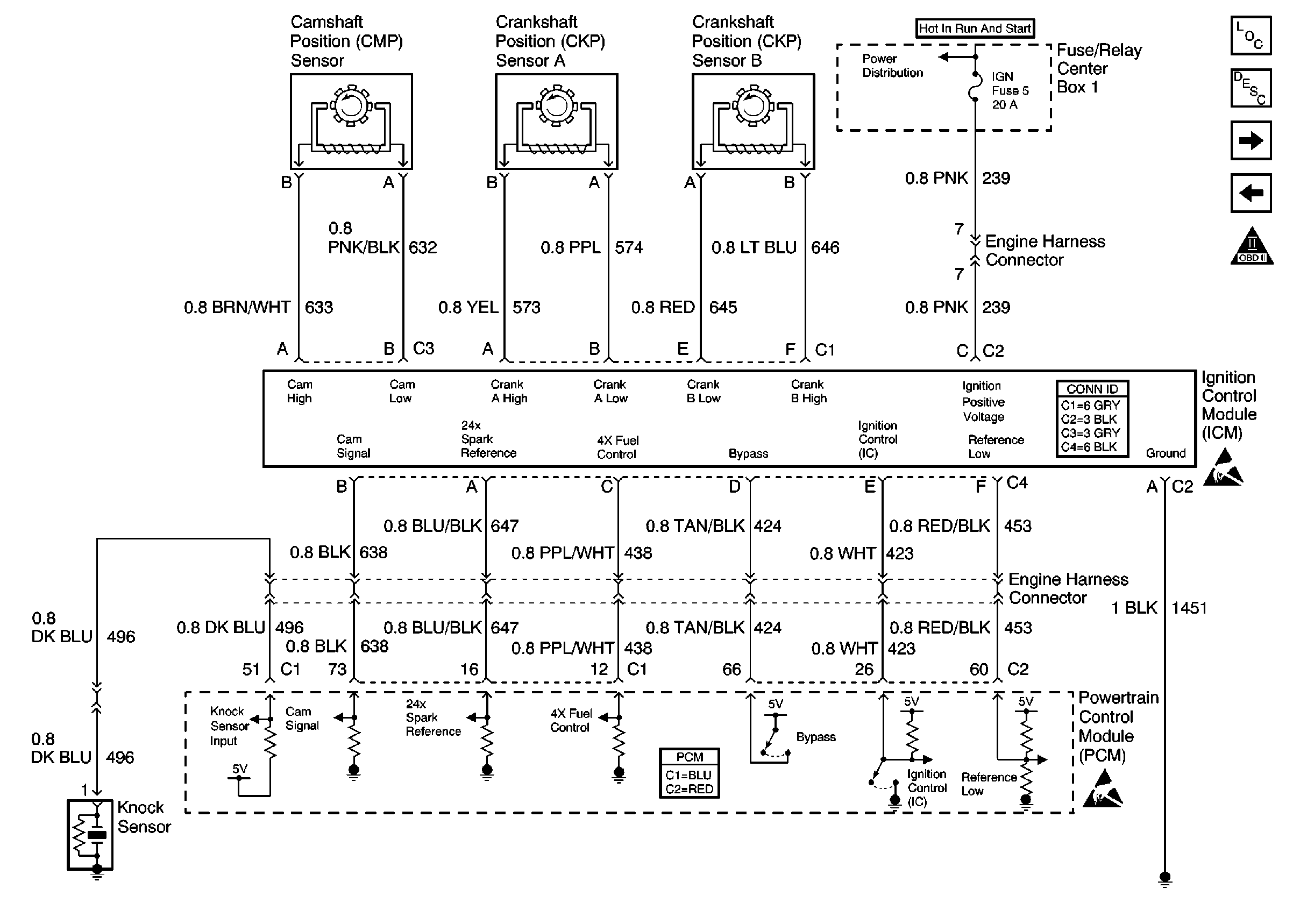
|
| Figure 4: |
Fuel System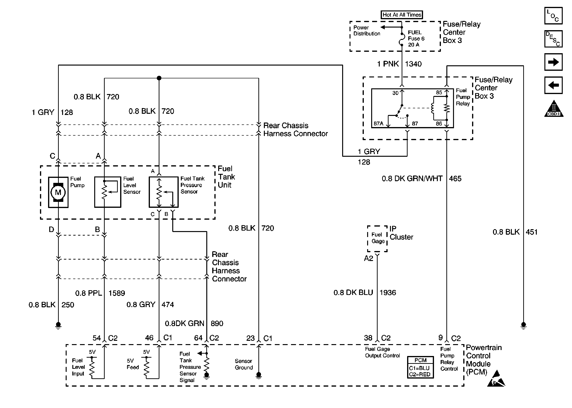
|
| Figure 5: |
Information Sensors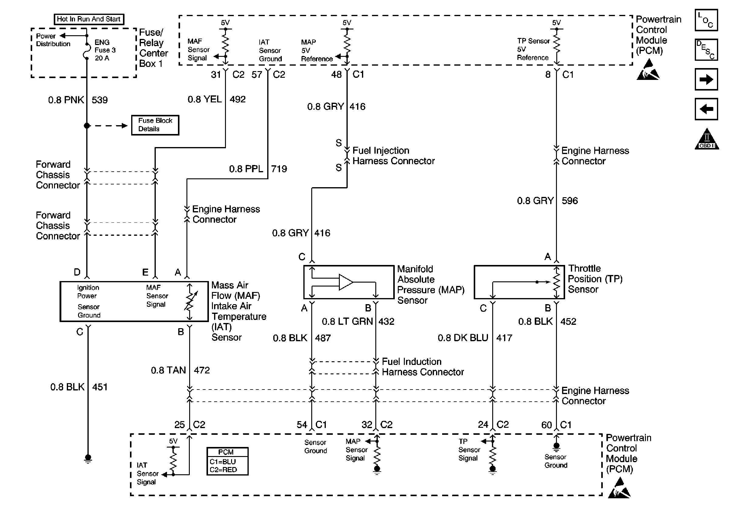
|
| Figure 6: |
Fuel Injectors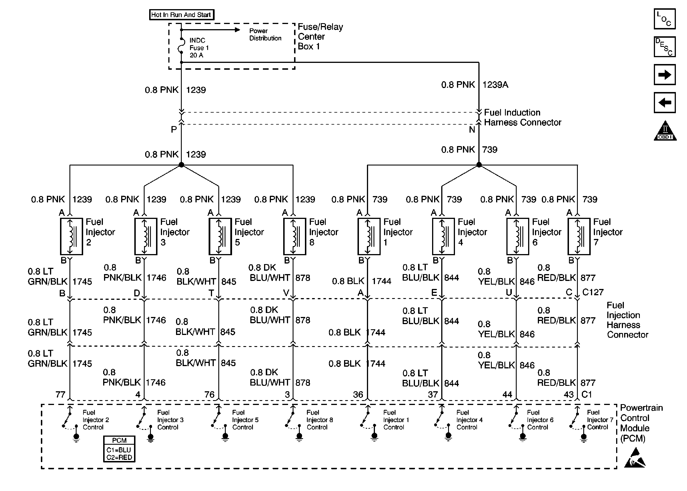
|
| Figure 7: |
Heated Oxygen Sensors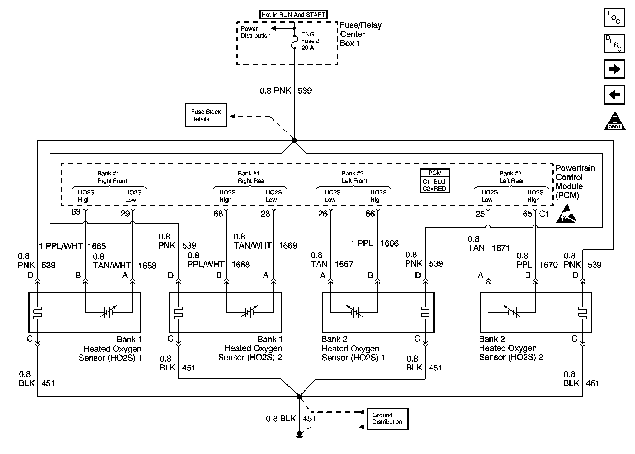
|
| Figure 8: |
Rough Road, Generator and IAC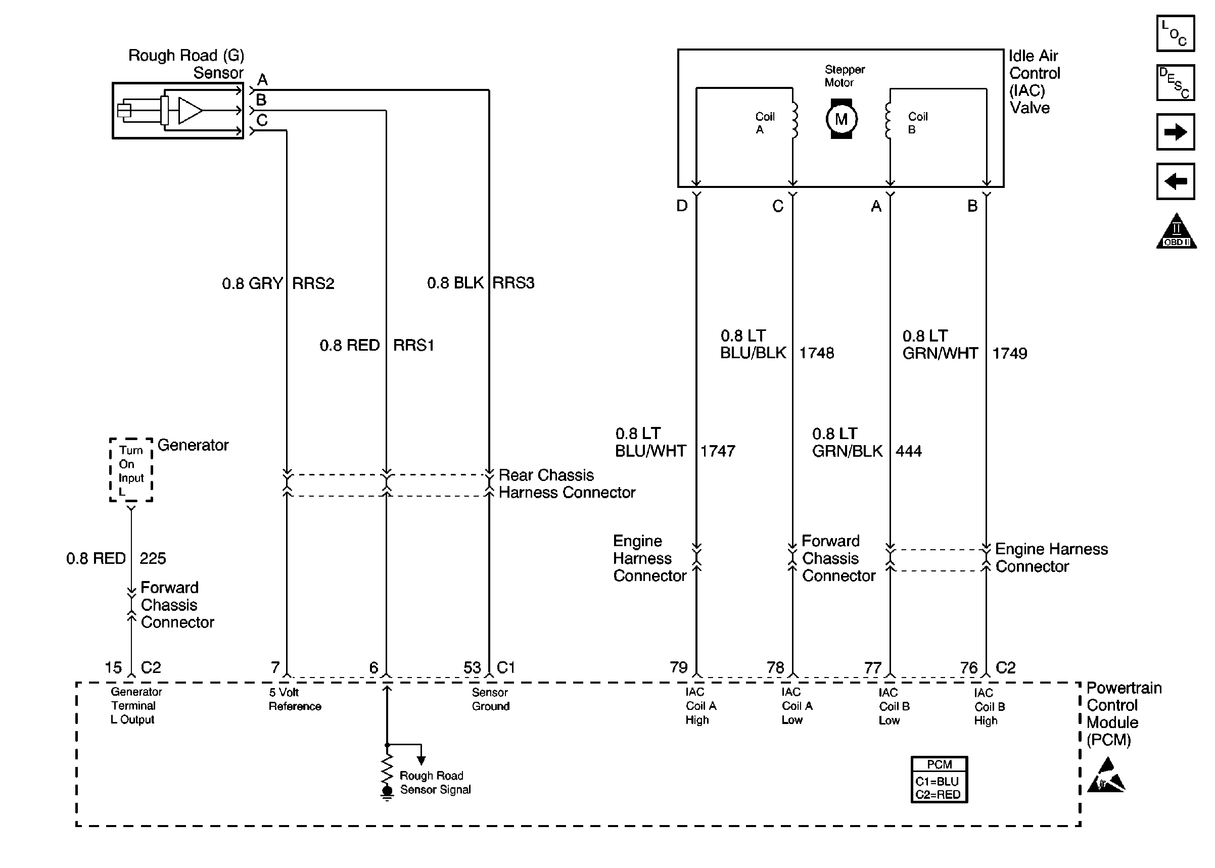
|
| Figure 9: |
Tach, Clutch Switch, VSS Output and VSS Signal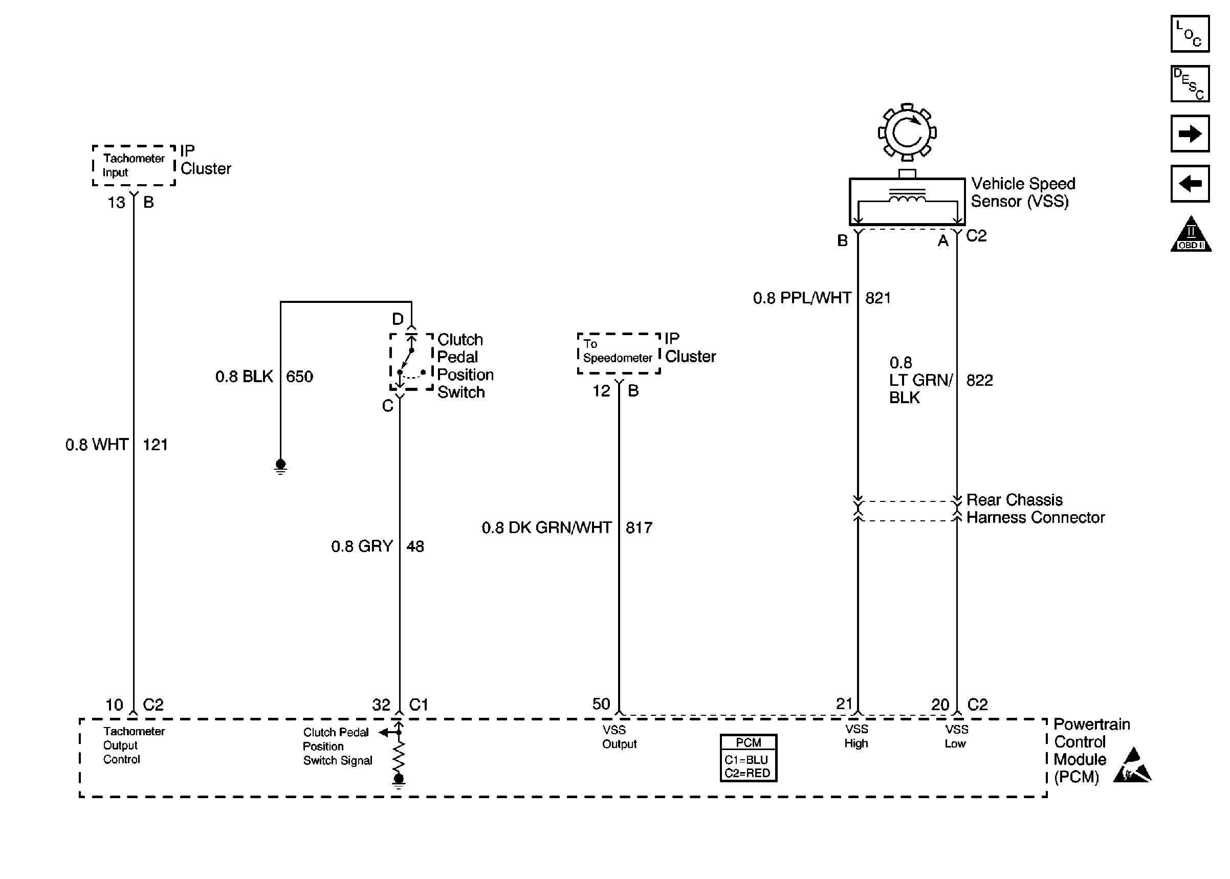
|
| Figure 10: |
EVAP and ECT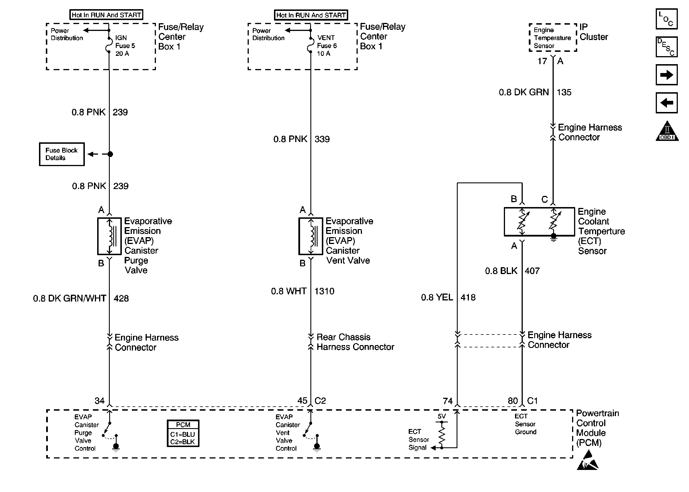
|
| Figure 11: |
A/C System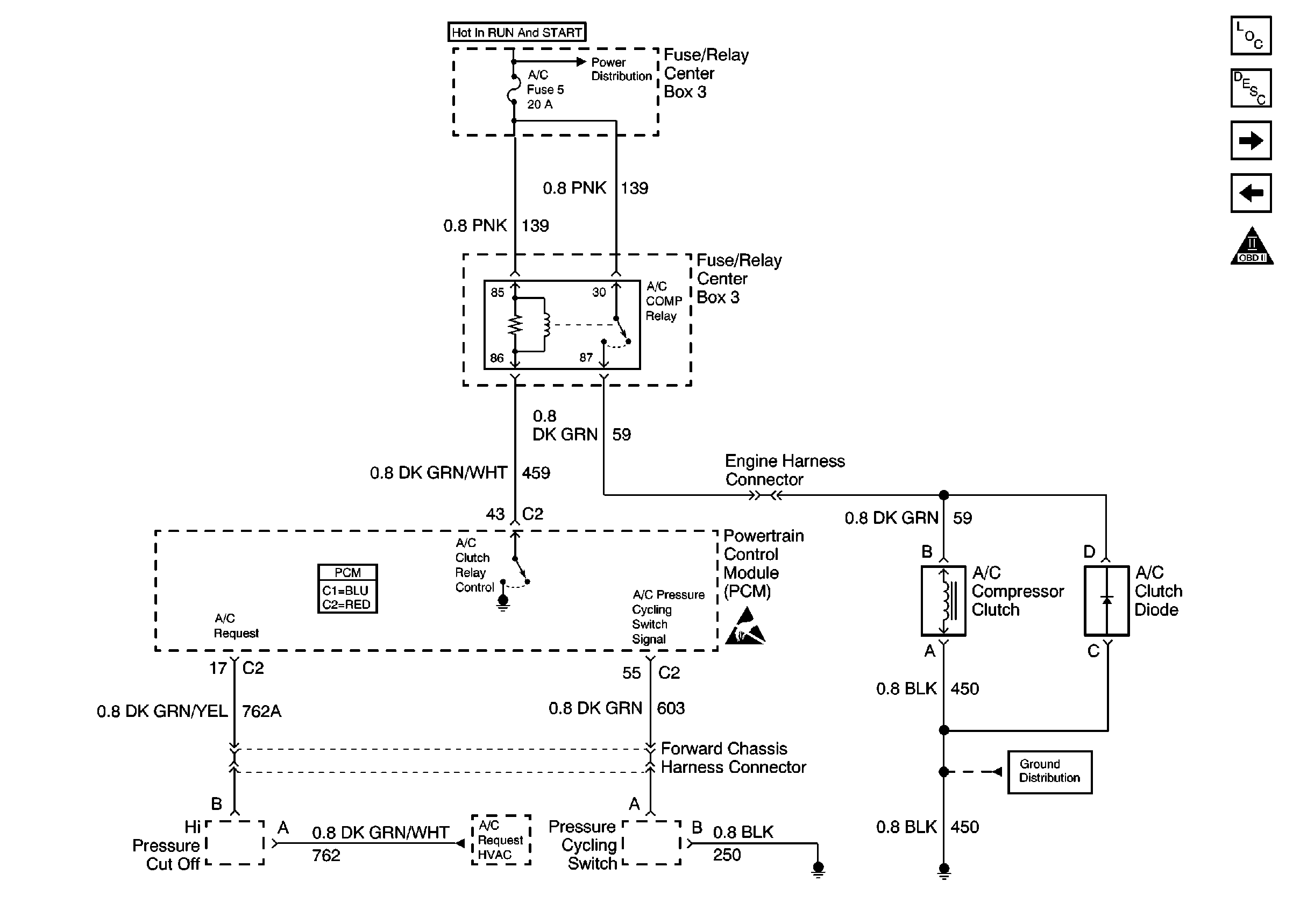
|
| Figure 12: |
Engine Cooling Fans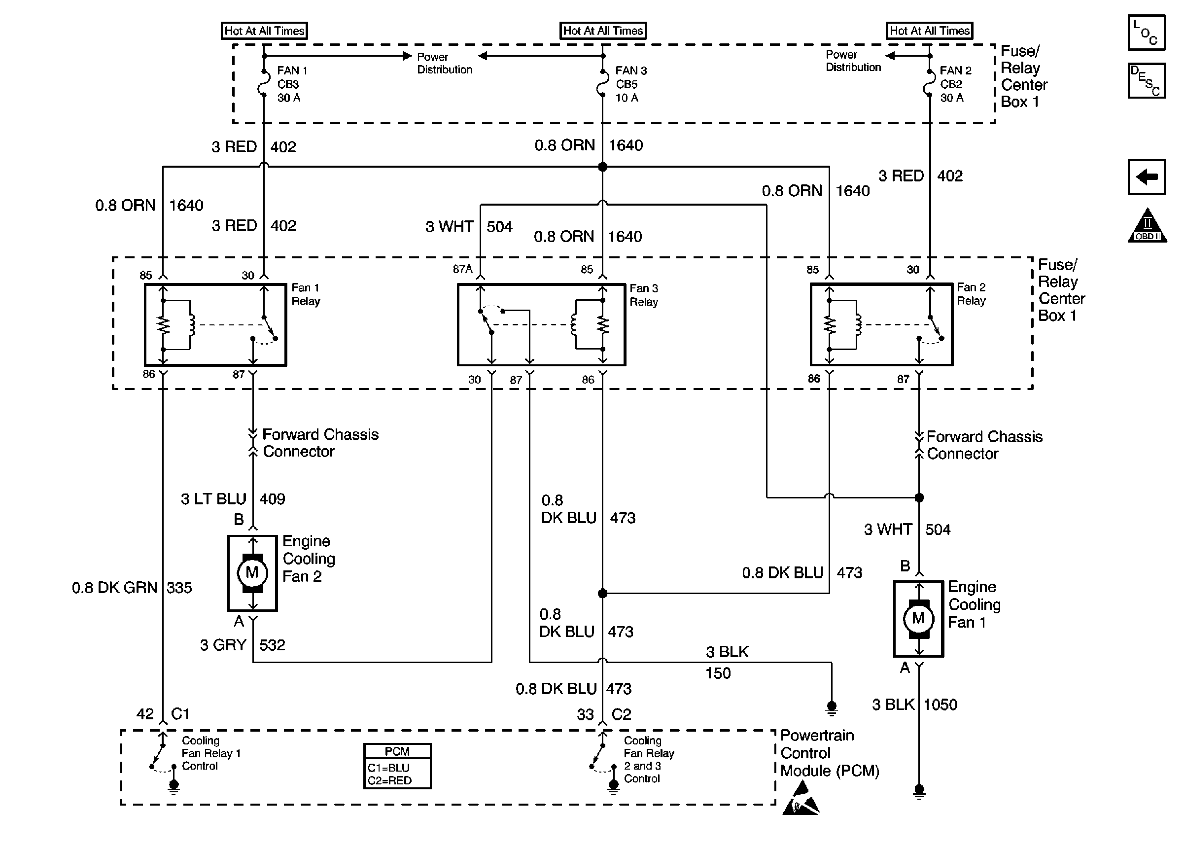
|
