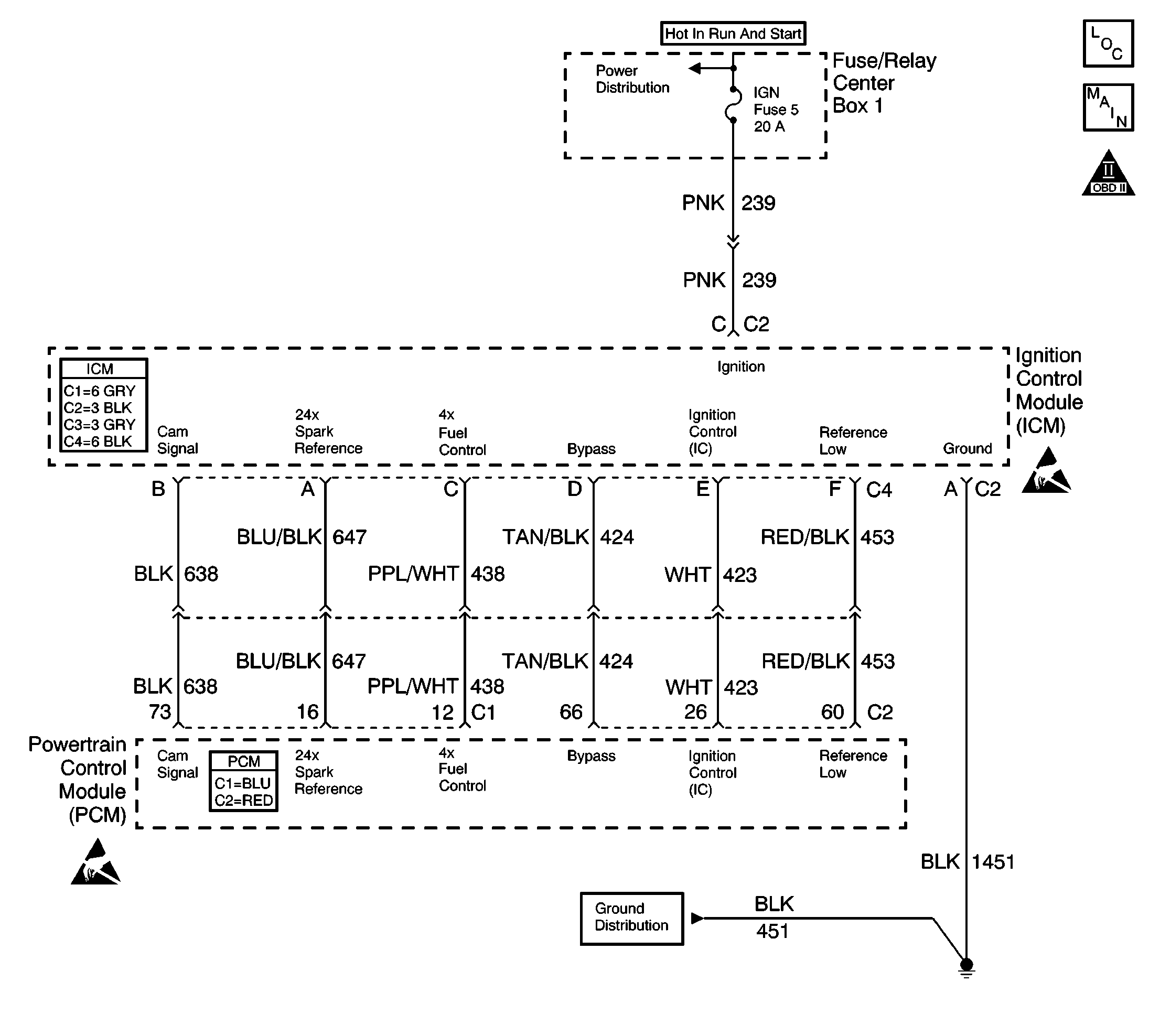
Circuit Description
The powertrain control module (PCM) checks for CAM pulses being received without 4X reference pulses.
Conditions for Running the DTC
| • | DTC P0340 is not set. |
| • | The engine speed is above 496 RPM. |
| • | The ignition voltage is above 6 volts. |
| • | A CAM sensor signal has been received in the last 4 seconds. |
Conditions for Setting the DTC
No 4X reference pulses received for 4 seconds.
Action Taken When the DTC Sets
PCM uses 24X signal for ignition and fuel control.
| • | The malfunction indicator lamp (MIL) will not illuminate. |
| • | The PCM will command a message to be displayed. |
| • | The PCM records the operating conditions at the time the diagnostic fails. This information will be stored in the Failure Records. |
Conditions for Clearing the Message/DTC
| • | The PCM will turn the message OFF after one run and pass of the diagnostic test. |
| • | A History DTC will clear after forty consecutive warm-up cycles with no failures of any non-emission related diagnostic test. |
| • | A last test failed, or current DTC, will clear when the diagnostic runs and does not fail. |
| • | Use a scan tool in order to clear DTCs. |
Test Description
The numbers below refer to the step numbers on the diagnostic table.
-
Using Freeze Frame and Failure Records may help locate an intermittent condition. Operate the vehicle within the same conditions that you observed in the Freeze Frame and Failure Records.
-
This step is testing the ignition control module (ICM) 4X signal circuit for a short to voltage.
-
This step is testing the continuity of the 4X signal circuit. If the DMM displays OL, an open circuit, or poor PCM connection is indicated.
-
This step is testing the 4X signal circuit and the PCM. If the resistance value displayed on the DMM changes as the ignition is turned OFF, then the 4X signal circuit and the PCM are OK.
-
This step is testing the ground circuit for the ICM. An open ground circuit can cause a variety of ignition control concerns.
Step | Action | Value(s) | Yes | No |
|---|---|---|---|---|
1 | Did you perform the Powertrain On-Board Diagnostic (OBD) System Check? | -- | Go to Step 2 | |
Does the scan tool indicate that this diagnostic failed this ignition? | -- | Go to Diagnostic Aids | ||
Is the voltage the less than the value specified? | 0.5 volts | |||
Measure the continuity of the 4X signal circuit with the DMM connected to battery ground. Refer to Testing for Continuity in Wiring Systems. Does the DMM display OL? | -- | |||
Does the resistance value change when the ignition is turned OFF. | -- | |||
Does the DMM display continuity? | -- | |||
7 |
Did you find and correct the condition? | -- | ||
8 |
Did you find and correct the condition? | -- | ||
9 |
Did you find and correct the condition? | -- | ||
10 | Repair the ICM ground circuit for an open. Refer to Wiring Repairs in Wiring Systems. Is the action complete? | -- | -- | |
11 | Repair the ICM 4X circuit for a short to voltage. Refer to Wiring Repairs in Wiring Systems. Is the action complete? | -- | -- | |
12 | Replace the ICM. Refer to Ignition Control Module Replacement . Is the action complete? | -- | -- | |
13 |
Important: The replacement PCM must programmed. Replace the PCM. Refer to Powertrain Control Module Replacement/Programming . Is the action complete? | -- | -- | |
14 |
Does the scan tool indicate that this test ran and passed? | -- | ||
15 | Select the Capture Info option and the Review Info option with the scan tool. Does the scan tool display any DTCs that you have not diagnosed? | -- | Go to the applicable DTC table | System OK |
