Cylinder Head Replacement Right Side
Removal Procedure
- Raise and suitably support the vehicle. Refer to SECTION 0A.
- Drain the coolant. Refer to Cooling System Draining and Filling in Engine Cooling.
- Remove the catalytic converter. Refer to Catalytic Converter Replacement in Engine Exhaust.
- Lower the vehicle.
- Remove the intake manifold. Refer to Intake Manifold Replacement .
- Remove the secondary air injection hose from the check valve.
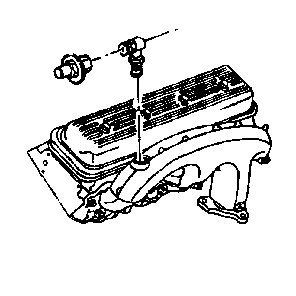
- Remove the engine coolant bleed pipe bolt from the left cylinder head using a backup wrench on the pipe fitting.
- Remove the ignition coil bolts and the coil.
- Remove the left exhaust manifold. Refer to Exhaust Manifold Replacement .
- Remove the spark plug wire harness from the clips.
- Remove the spark plug wire harness from the spark plugs.
- Remove the spark plugs.
- Remove the coolant temperature sensor electrical connector.
- Remove the valve rocker arm cover bolts and the cover. Refer to Valve Rocker Arm Cover Replacement .
- Remove the valve rocker arms and pushrods. Refer to Valve Rocker Arm, Push Rod, and Stud Replacement .
- Remove the cylinder head bolts.
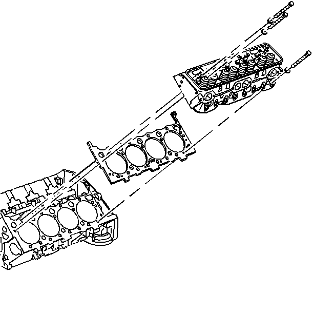
- Remove the cylinder head and the cylinder head gasket.
- Discard the cylinder head gasket.


Installation Procedure
- Install the new cylinder head gasket with the yellow tab facing up.
- Install the cylinder head over the locator pins and the cylinder head gasket.
- Coat the threads of the cylinder head bolts with the sealing compound, GM P/N 12346004 or the equivalent.
- Install the cylinder head bolts finger tight.
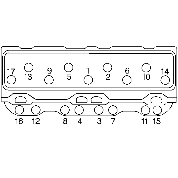
- Tighten the cylinder head bolts in sequence on the first pass.
- Use the J 36660 in order to tighten the cylinder head bolts on the second pass.
- Install the pushrods and the valve rocker arms. Refer to Valve Rocker Arm, Push Rod, and Stud Replacement .
- Install the left valve rocker arm cover and the bolts.
- Install the coolant temperature sensor electrical connector.
- Install the spark plugs.
- Install the spark plug wire harness to the spark plugs.
- Install the spark plug wire harness to the clips.
- Install the left exhaust manifold. Refer to Exhaust Manifold Replacement .
- Install the ignition coil bolts and the coil.
- Install the engine coolant air bleed pipe and the bolt to the left cylinder head using a backup wrench on the pipe fitting.
- Install the secondary air injection hose to the check valve.
- Install the intake manifold. Refer to Intake Manifold Replacement .
- Raise and suitably support the vehicle. Refer to SECTION 0A.
- Install the catalytic converter. Refer to Catalytic Converter Replacement in Engine Exhaust.
- Lower the vehicle.
- Refill with coolant. Refer to Cooling System Draining and Filling in Engine Cooling.

Important: When installing the cylinder head bolts, mark the short bolts for identification after installation in order to ensure that the correct torque specifications are met.

Tighten
Tighten the cylinder head bolts in sequence to 30 N·m (22 lb ft).
Notice: Use the correct fastener in the correct location. Replacement fasteners must be the correct part number for that application. Fasteners requiring replacement or fasteners requiring the use of thread locking compound or sealant are identified in the service procedure. Do not use paints, lubricants, or corrosion inhibitors on fasteners or fastener joint surfaces unless specified. These coatings affect fastener torque and joint clamping force and may damage the fastener. Use the correct tightening sequence and specifications when installing fasteners in order to avoid damage to parts and systems.
Tighten
| • | Tighten the short length bolts (3, 4, 7, 8, 11, 12, 15, 16) 67 degrees. |
| • | Tighten the medium length bolts (14, 17) 80 degrees. |
| • | Tighten the long length bolts (1, 2, 5, 6, 9, 10, 13) 67 degree. |

Tighten
Tighten the valve rocker arm cover bolts to 12 N·m (106 lb in).
Tighten
Tighten the spark plugs to 20 N·m (15 lb ft).
Tighten
Tighten the ignition coil studs to 40 N·m (30 lb ft).
Tighten
Tighten the engine coolant bleed pipe bolt to 40 N·m (30 lb ft).

Cylinder Head Replacement Left Side
Removal Procedure
- Raise and suitably support the vehicle. Refer to SECTION 0A.
- Drain the coolant. Refer to Cooling System Draining and Filling in Engine Cooling.
- Remove the accessory drive belt. Refer to Drive Belt Replacement .
- Remove the accessory drive belt tensioner. Refer to Drive Belt Tensioner Replacement .
- Remove the automatic transmission fluid level indicator tube bracket from the transmission housing.
- Remove the air conditioning compressor rear brace bolt from the engine block.
- Remove the air conditioning compressor electrical connector.
- Remove the air conditioning compressor front mounting bolts and lay the air conditioning compressor aside.
- Remove the right exhaust manifold. Refer to Exhaust Manifold Replacement .
- Lower the vehicle.
- Remove the generator.
- Remove the right valve rocker arm cover.
- Remove the intake manifold. Refer to Intake Manifold Replacement .
- Remove the engine coolant air bleed pipe bolt from the right cylinder head using a backup wrench on the pipe fitting.
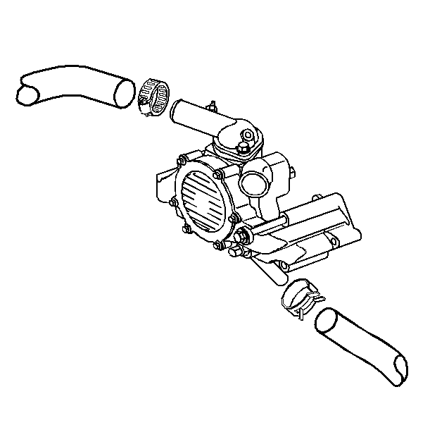
- Lower the radiator hose from the water pump and reposition.
- Remove the heater hose from the water pump and reposition.
- Remove the engine coolant air bleed pipe hose from the radiator.
- Remove the power steering pump. Refer to SECTION 3B.
- Remove the following parts:
- Remove the spark plug wire harness from the spark plugs.
- Remove the spark plugs.
- Remove the valve rocker arms and pushrods. Refer to Valve Rocker Arm, Push Rod, and Stud Replacement .
- Remove the cylinder head bolts.
- Remove the cylinder head and the cylinder head gasket.
- Discard the cylinder head gasket.
- Remove the engine coolant air bleed pipe bolt using a backup wrench on the pipe fitting.
- Remove the nut and pipe from the cylinder head.


| • | The generator bracket bolts |
| • | The generator |
| • | The air conditioning compressor |
| • | The power steering pump bracket |

Installation Procedure
- Install the new cylinder head gasket with the yellow tab facing up.
- Install the cylinder head over the dowel pins and the gasket.
- Coat the threads of the cylinder head bolts with sealing compound GM P/N 1052080 or the equivalent.
- Tighten the cylinder head bolts in sequence on the first pass.
- Use the J 36660 in order to tighten the cylinder head bolts on the second pass.
- Install the pushrods and the valve rocker arms. Refer to Valve Rocker Arm, Push Rod, and Stud Replacement .
- Install the spark plugs.
- Install the spark plug wire harness to the spark plugs.
- Install the following parts:
- Install the generator bracket bolts.
- Install the right valve rocker arm cover.
- Install the generator.
- Install the power steering pump. Refer to SECTION 3B.
- Install the engine coolant air bleed pipe hose to the radiator.
- Install the heater hose to the water pump and reposition.
- Install the lower radiator hose to the water pump.
- Install the engine coolant air bleed pipe bolt to the left cylinder head using a backup wrench.
- Install the intake manifold. Refer to Intake Manifold Replacement .
- Raise and suitably support the vehicle. Refer to SECTION 0A.
- Install the right exhaust manifold. Refer to Exhaust Manifold Replacement .
- Install the air conditioning compressor.
- Install the air conditioning compressor electrical connector.
- Install the air conditioning compressor rear brace bolt to the engine block.
- Install the automatic transmission fluid level indicator tube bracket to the transmission housing.
- Install the accessory drive belt. Refer to Drive Belt Replacement .
- Install the drive belt tensioner. Refer to Drive Belt Tensioner Replacement .
- Lower the vehicle.
- Refill with coolant. Refer to Cooling System Draining and Filling in Engine Cooling.

Important: When installing the cylinder head bolts, mark the short bolts for identification after installation in order to ensure that the correct torque specifications are met.

Tighten
Tighten the cylinder head bolts in sequence to 30 N·m (22 lb ft).
Notice: Use the correct fastener in the correct location. Replacement fasteners must be the correct part number for that application. Fasteners requiring replacement or fasteners requiring the use of thread locking compound or sealant are identified in the service procedure. Do not use paints, lubricants, or corrosion inhibitors on fasteners or fastener joint surfaces unless specified. These coatings affect fastener torque and joint clamping force and may damage the fastener. Use the correct tightening sequence and specifications when installing fasteners in order to avoid damage to parts and systems.
Tighten
| • | Tighten the short length bolts (3, 4, 7, 8, 11, 12, 15, 16) 67 degrees. |
| • | Tighten the medium length bolts (14, 17) 80 degrees. |
| • | Tighten the long length bolts (1, 2, 5, 6, 9, 10, 13) 67 degrees. |
Tighten
| • | Tighten the engine coolant air bleed pipe bolt/screw to 40 N·m (30 lb ft). |
| • | Tighten the engine coolant air bleed pipe nut to 17 N·m (13 lb ft). |
Tighten
Tighten the spark plugs to 20 N·m (15 lb ft).
| • | The generator |
| • | The air conditioning compressor |
| • | The power steering pump bracket |
Tighten
Tighten the generator bracket bolts to 40 N·m (30 lb ft).


Tighten
Tighten the engine coolant air bleed pipe bolt to 40 N·m
(30 lb ft).
Tighten
Tighten the air conditioning compressor rear brace bolt to 33 N·m
(24 lb ft).
