- Remove the J 39430
from the transmission.
- Mount the transmission assembly on a suitable safety stand.
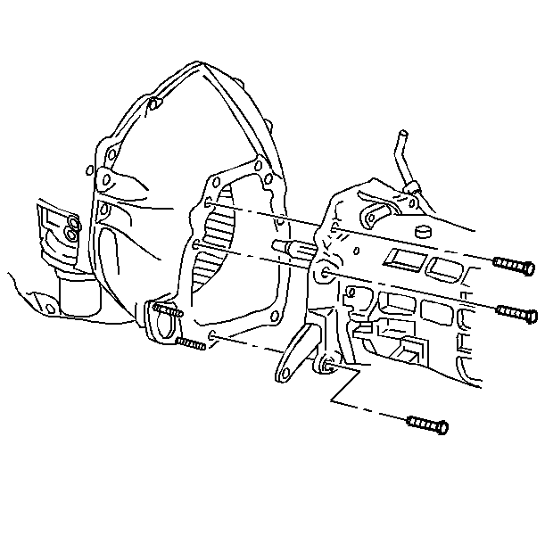
- Perform the following:
| 3.1. | Align the transmission assembly to the flywheel housing. |
| 3.2. | Guide the input shaft into the clutch disc hub and into the flywheel
pilot bearing. |
| 3.3. | Install the transmission to flywheel housing bolts. |
Tighten
Tighten the bolts to 43 N·m (35 lb ft). Refer
to
Notice: Use the correct fastener in the correct location. Replacement fasteners
must be the correct part number for that application. Fasteners requiring
replacement or fasteners requiring the use of thread locking compound or sealant
are identified in the service procedure. Do not use paints, lubricants, or
corrosion inhibitors on fasteners or fastener joint surfaces unless specified.
These coatings affect fastener torque and joint clamping force and may damage
the fastener. Use the correct tightening sequence and specifications when
installing fasteners in order to avoid damage to parts and systems.
in General Information.
- Install the transmission support-mount assembly. Refer to Transmission Support and Mount Assembly
.
- Remove the transmission assembly safety stand.
- Remove the engine safety stand.
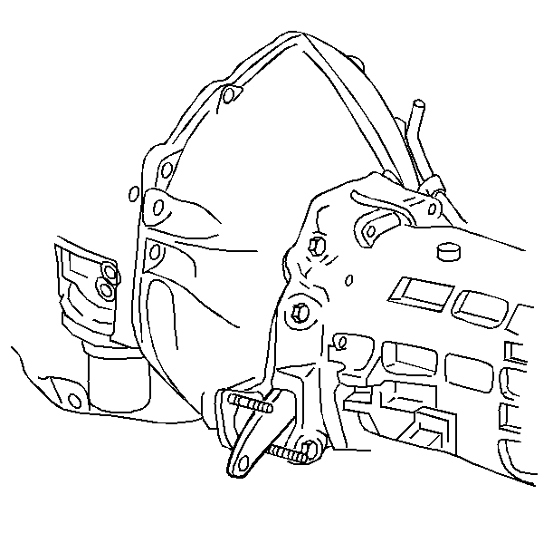
- Push the clutch fork assembly up until
it engages the release bearing.
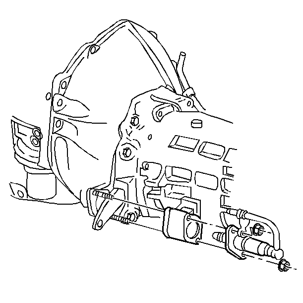
- Install the following:
| 8.2. | The clutch actuator cylinder |
| 8.3. | The actuator cylinder nuts |
Tighten
Tighten the nuts to 20 N·m (15 lb ft).
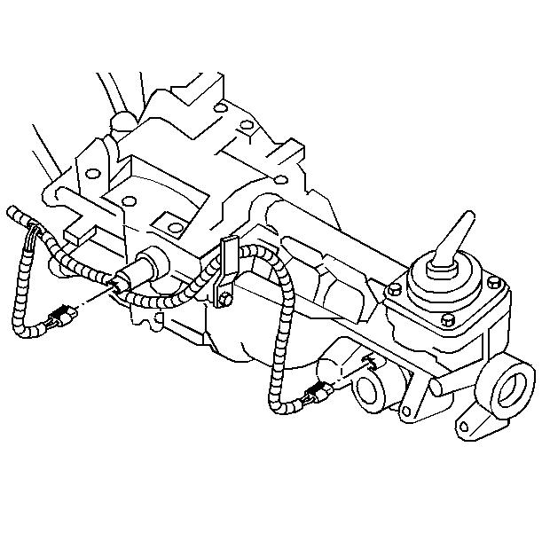
- Connect the following wire harness connectors:
| • | The vehicle speed sensor |
| • | The ship shift solenoid |
| • | The reverse lockout solenoid |
- Install the catalytic converter hanger assembly. Refer to
Converter Hanger Assembly
in Engine Exhaust.
- Install the rear axle torque arm assembly. Refer to Rear Axle
Torque Arm Replacement in Rear Suspension.
- Install the propeller shaft assembly. Refer to Propeller Shaft
Replacement in Propeller Shaft.
- Check the transmission fluid level. Refer to
Transmission Fluid Inspection
.
- Remove the safety stands.
- Lower the vehicle.
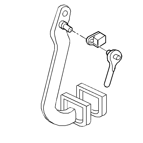
- Connect the clutch pushrod to the clutch
pedal assembly pin.
- Connect the pin retainer to the clutch pushrod.
- Install the left-hand Instrument panel sound insulator assembly.
Refer to Instrument Panel Insulator Replacement in Instrument Panel, Gauges,
and Console.
- Install the control lever handle. Refer to Control Lever Handle Assembly (6-Speed)
.
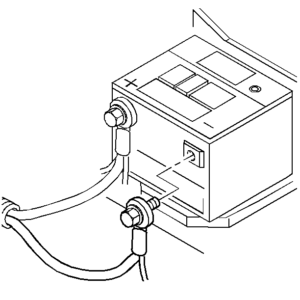
- Connect the battery negative cable assembly
to the battery negative terminal.
Tighten
Tighten the terminal bolt to 15 N·m (11 lb ft).


