For 1990-2009 cars only
Power Vacuum Brake Booster Replacement Left-Hand Drive
Removal Procedure
- Remove the master cylinder assembly. Refer to Master Cylinder Replacement.
- Disconnect the vacuum hose from the power booster.
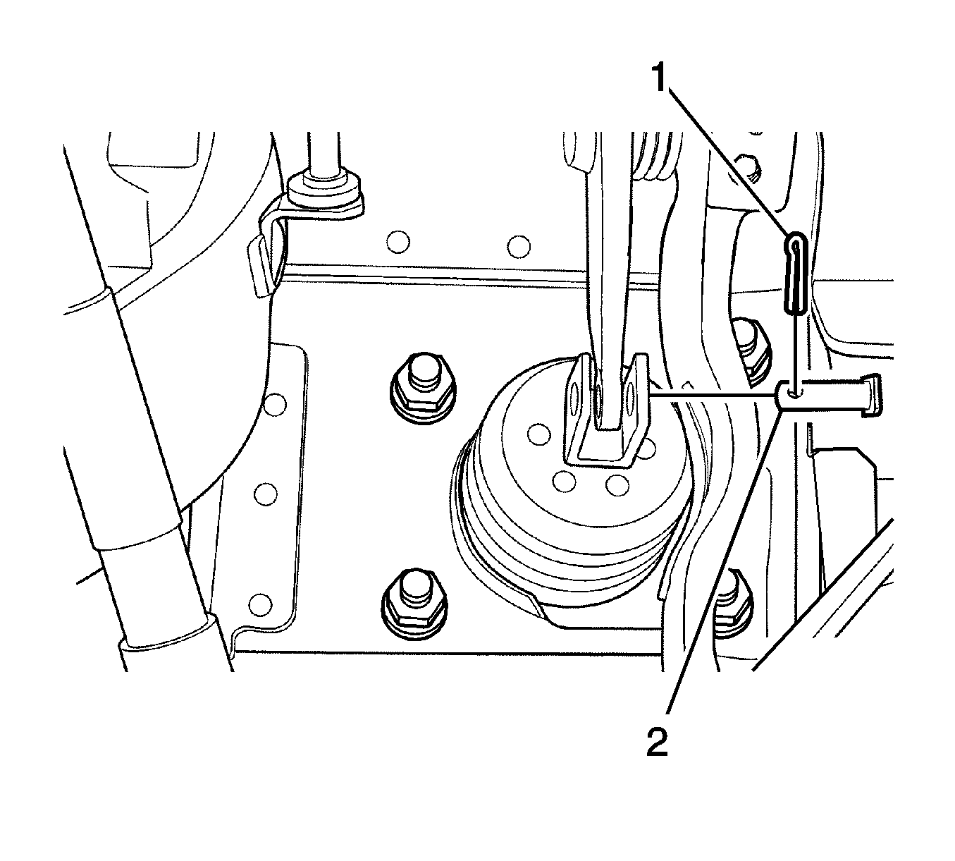
- Straighten the cotter pin and remove it (1).
- Remove the clevis pin (2).
- Remove the nuts (1).
- Remove the power booster (1).


Installation Procedure
- Install the power booster with the new cotter pin, clevis pin and nuts (1). Tighten the nuts to 16 N·m (12 lb ft).
- Install the master cylinder assembly. Refer to Master Cylinder Replacement.
- Connect the vacuum hose to the power booster.
- Bleed the brake system. Refer to Hydraulic Brake System Bleeding.
Caution: Refer to Fastener Caution in the Preface section.

Note: Make sure the distance from the booster to the center of the clevis bore should be 100 mm (3.94 in).
Power Vacuum Brake Booster Replacement Right-Hand Drive
Removal Procedure
- Remove the master cylinder assembly. Refer to Master Cylinder Replacement.
- Disconnect the vacuum hose from the vacuum brake booster.
- Remove the instrument panel assembly. Refer to Instrument Panel Assembly Replacement.
- Remove the evaporator unit mounting screws and move the evaporator unit to the side. Refer to Air Conditioning Evaporator Core Replacement.
- Remove the cotter pin (1).
- Remove the clevis pin (2).
- Remove the nuts (1).
- Remove the booster (1).


Installation Procedure
- Verify the distance from the vacuum brake booster to the center of the clevis bore is correct.
- Install the booster with the new cotter pin, clevis pin and nuts (1). Tighten the nuts to 16 N·m (12 lb ft).
- Install the evaporator unit with the screws. Refer to Air Conditioning Evaporator Core Replacement.
- Install the instrument panel assembly. Refer to Instrument Panel Assembly Replacement.
- Connect the vacuum hose to the booster.
- Install the master cylinder assembly. Refer to Master Cylinder Replacement.
Specification
The correct distance from the booster to the center of the clevis bore is 100 mm (3.94 in).
Caution: Refer to Fastener Caution in the Preface section.

