All of the sensors and input switches can be diagnosed using a scan tool. Following is a short description of how the sensors and switches can be diagnosed by using a scan tool. The scan tool can also be used to compare the values for a normal running engine with the engine you are diagnosing.
Engine Coolant Temperature (ECT) Sensor
The engine coolant temperature sensor is a thermistor (a resistor which changes value based on temperature) mounted in the engine coolant stream.
Low coolant temperature produces a high resistance (100,000 ohms at -40°C/-40°F) while high temperature causes low resistance (70 ohms at 130°C/266°F).
The PCM supplies a 5.0 volt signal to the engine coolant temperature sensor through a resistor in the PCM, and measures the voltage. The voltage will be high when the engine is cold, and low when the engine is hot. By measuring the voltage, the PCM calculates the engine coolant temperature. Engine coolant temperature affects most systems the PCM controls.
The scan tool displays engine coolant temperature in degrees. After engine startup, the temperature should rise steadily to about 90°C (194°F) then stabilize when thermostat opens. If the engine has not been run for several hours (overnight), the engine coolant temperature and intake air temperature displays should be close to each other. A hard fault in the engine coolant sensor circuit should set DTC P0117 Engine Coolant Temperature (ECT) Sensor Circuit Low Voltage , or DTC P0118 Engine Coolant Temperature (ECT) Sensor Circuit High Voltage , an intermittent fault should set a DTC P1114 Engine Coolant Temperature (ECT) Sensor Circuit Intermittent Low Voltage , or DTC P1115 Engine Coolant Temperature (ECT) Sensor Circuit Intermittent High Voltage . The DTC Diagnostic Aids also contains a chart to check for sensor resistance values relative to temperature.
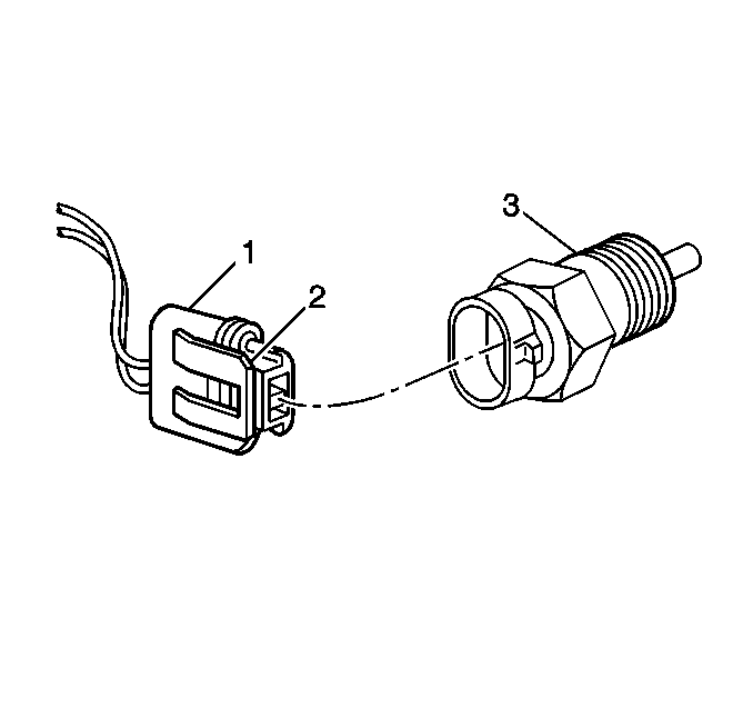
The ECT sensor (3) also contains another circuit which is used to operate the engine coolant temperature gauge located in the instrument panel.
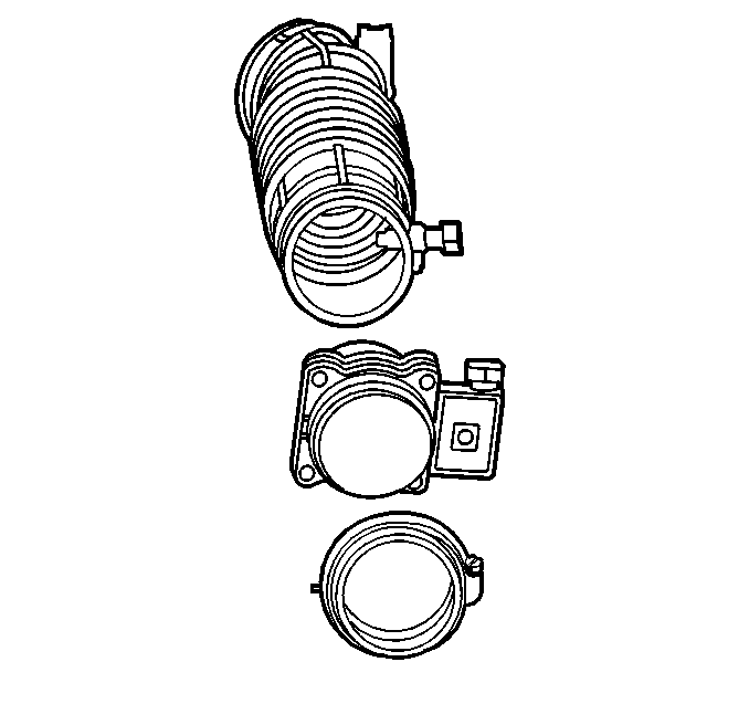
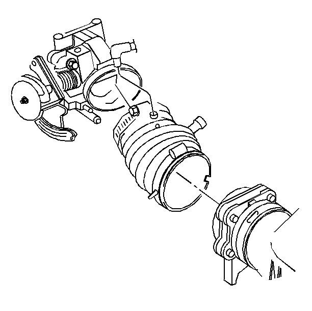
Mass Air Flow (MAF) Sensor
The mass air flow (MAF) sensor measures the amount of air which passes through it. The PCM uses this information to determine the operating condition of the engine, to control fuel delivery.
A large quantity of air indicates acceleration, while a small quantity indicates deceleration or idle.
The scan tool reads the MAF value and displays it in grams per second (gm/s). At idle, it should read between 4gm/s to 6gm/s on a fully warmed up engine. Values should change rather quickly on acceleration, but values should remain fairly stable at any given RPM. A failure in the MAF sensor or circuit should set DTC P0101 Mass Air Flow (MAF) Sensor Performance , DTC P0102 Mass Air Flow (MAF) Sensor Circuit Low Frequency , or DTC P0103 Mass Air Flow (MAF) Sensor Circuit High Frequency .
Intake Air Temperature (IAT) Sensor
The intake air temperature (IAT) sensor is a thermistor which changes value based on the temperature of air entering the engine. Low temperature produces a high resistance (100,000 ohms at -40°C/-40°F), while high temperature causes low resistance (70 ohms at 130°C/266°F).
The PCM supplies a 5.0 volt signal to the sensor through a resistor in the PCM and measures the voltage. The voltage will be high when the incoming air is cold, and low when the air is hot. By measuring the voltage, the PCM calculates the incoming air temperature. The IAT sensor signal is used to adjust spark timing according to incoming air density.
The scan tool displays temperature of the air entering the engine, which should read close to ambient air temperature when the engine is cold, and rise as the underhood temperature increases.
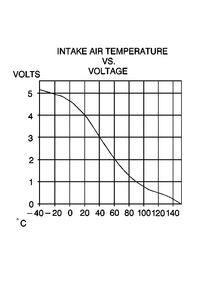
If the engine has not been run for several hours (overnight) the IAT sensor temperature and engine coolant temperature should read close to each other. A failure in the IAT sensor circuit should set DTC P0112 Intake Air Temperature (IAT) Sensor Circuit Low Voltage or DTC P0113 Intake Air Temperature (IAT) Sensor Circuit High Voltage .
Manifold Absolute Pressure (MAP) Sensor
The manifold absolute pressure (MAP) sensor responds to changes in intake manifold pressure (vacuum). The MAP sensor signal voltage to the PCM varies from below 2.0 volts at idle (high vacuum) to above 4.0 volts with the key ON, engine not running or at wide open throttle (WOT) (low vacuum).
The MAP sensor is used to determine manifold pressure changes while the linear EGR flow test diagnostic is being run. Refer to DTC P0401 Exhaust Gas Recirculation (EGR) Flow Insufficient to determine engine vacuum level for other diagnostics, and to determine barometric pressure (BARO).
If the PCM detects a voltage that is lower than the possible range of the MAP sensor, DTC P0107 Manifold Absolute Pressure (MAP) Sensor Circuit Low Voltage will be set. A signal voltage higher than the possible range of the sensor will set DTC P0108 Manifold Absolute Pressure (MAP) Sensor Circuit High Voltage . An intermittent low or high voltage will set DTC P1107 Manifold Absolute Pressure (MAP) Sensor Circuit Intermittent Low Voltage or DTC P1106 Manifold Absolute Pressure (MAP) Sensor Circuit Intermittent High Voltage respectively. The PCM can also detect a shifted MAP sensor. The PCM compares the MAP sensor signal to a calculated MAP based on throttle position and various engine load factors
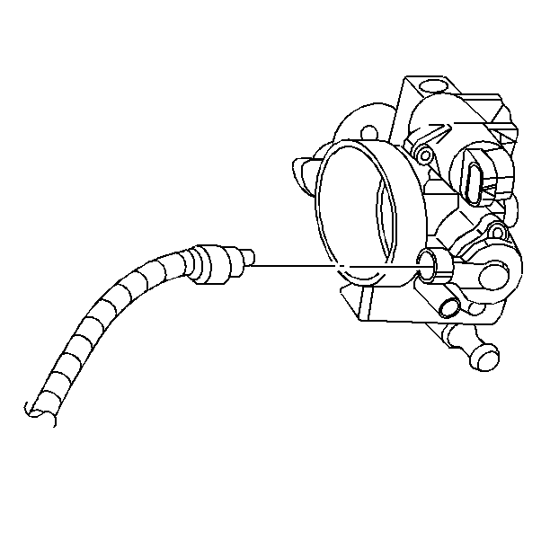
Fuel Control Heated Oxygen Sensor (HO2S 1)
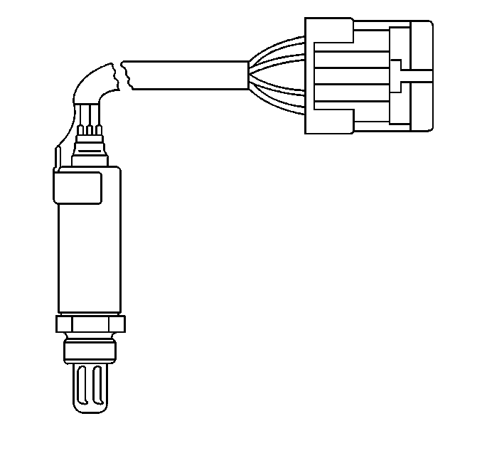
The fuel control heated oxygen sensor (HO2S 1) is mounted in the exhaust manifold where it can monitor the oxygen content of the exhaust gas stream. The oxygen present in the exhaust gas reacts with the sensor to produce a voltage output. This voltage should constantly fluctuate from approximately 100 mV (high oxygen content lean mixture) to 900 mV (low oxygen content rich mixture). The heated oxygen sensor voltage can be monitored with a scan tool. By monitoring the voltage output of the oxygen sensor, the PCM calculates what fuel mixture command to give to the injectors (lean mixture low HO2S voltage = rich command, rich mixture high HO2S voltage = lean command).

The HO2S 1 circuit, if open, should set a DTC P0134 HO2S Circuit Insufficient Activity Sensor 1 and the scan tool will display a constant voltage between 400-500 mV. A constant voltage below 300 mV in the sensor circuit (circuit grounded) should set DTC P0131 HO2S Circuit Low Voltage Sensor 1 , while a constant voltage above 800 mV in the circuit should set DTC P0132 HO2S Circuit High Voltage Sensor 1 . A fault in the HO2S 1 heater circuit should cause DTC P0135 to set. The PCM can also detect HO2S response problems. If the response time of an HO2S is determined to be too slow, the PCM will store a DTC that indicates degraded HO2S performance.
Throttle Position (TP) Sensor
The throttle position (TP) sensor is a potentiometer connected to the throttle shaft on the throttle body. By monitoring the voltage on the signal line, the PCM calculates throttle position. As the throttle valve angle is changed (accelerator pedal moved), the TP sensor signal also changes. At a closed throttle position, the output of the TP sensor is low. As the throttle valve opens, the output increases so that at wide open throttle (WOT), the output voltage should be above 4.0 volts.
The PCM calculates fuel delivery based on throttle valve angle (driver demand). A broken or loose TP sensor may cause intermittent bursts of fuel from an injector and unstable idle because the PCM thinks the throttle is moving.
A hard failure in the TP sensor 5.0 volt reference or signal circuits should set either a
A hard failure with the TP sensor ground circuit may set DTCs
Once a DTC is set, the PCM will use an artificial default value based on engine RPM, engine load, and mass air flow for throttle position and some vehicle performance will return. A high idle may result when either DTC P0122 Throttle Position (TP) Sensor Circuit Low Voltage or DTC P0123 Throttle Position (TP) Sensor Circuit High Voltage is set.
The PCM can detect intermittent TP sensor faults. DTC P1121 Throttle Position (TP) Sensor Circuit Intermittent High Voltage or DTC P1122 Throttle Position (TP) Sensor Circuit Intermittent Low Voltage will set if an intermittent high or low circuit failure is being detected.
The PCM can also detect a shifted TP sensor. The PCM monitors throttle position and compares the actual TP sensor reading to a predicted TP value calculated from engine speed. If the PCM detects an out of range condition, DTC P0121 Throttle Position (TP) Sensor Performance will be set.
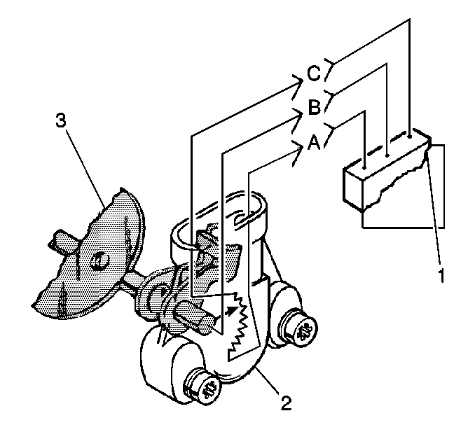
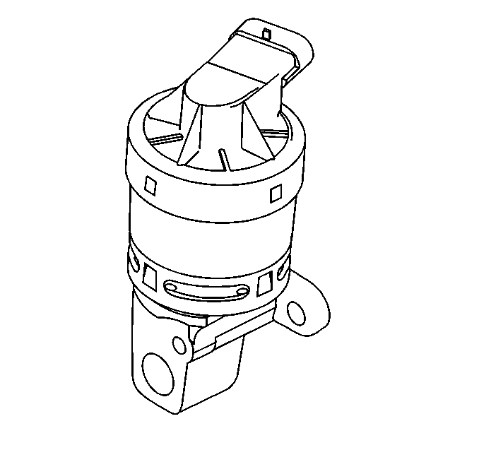
EGR Pintle Position Sensor
The EGR pintle position sensor is an integral part of the EGR valve assembly. This sensor can not be serviced separately from the EGR valve assembly.
The PCM monitors the EGR valve pintle position input to ensure that the valve responds properly to commands from the PCM and to detect a fault if the pintle position sensor and control circuits are open or shorted.
If the PCM detects a pintle position signal voltage outside the normal range of the pintle position sensor, or a signal voltage that is not within a tolerance considered acceptable for proper EGR system operation, the PCM will set DTC P1404 EGR Valve Stuck Open .
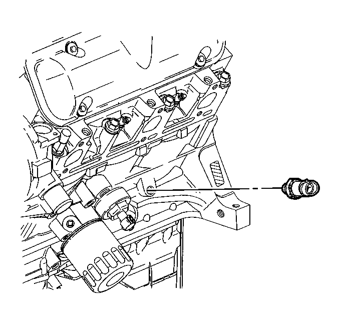
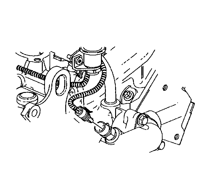
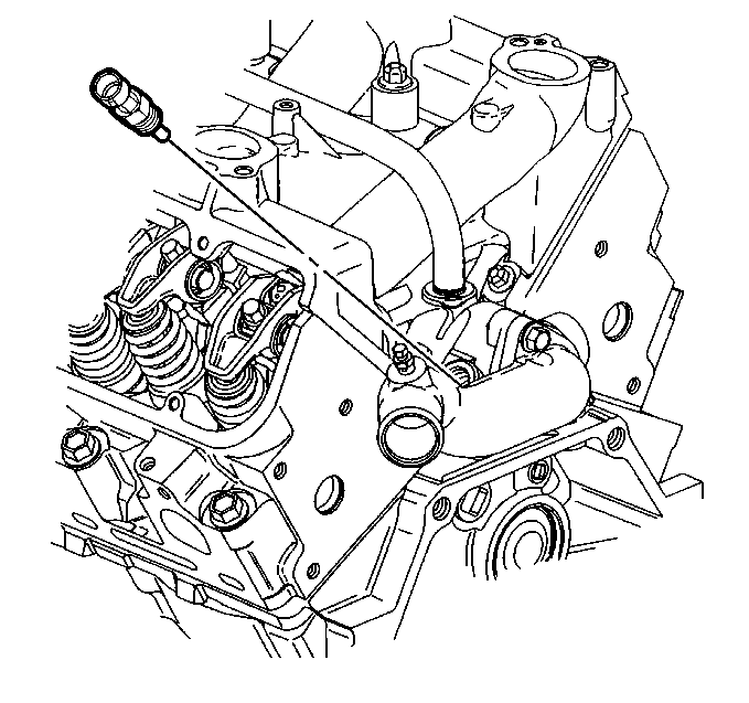
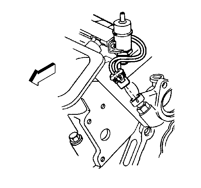
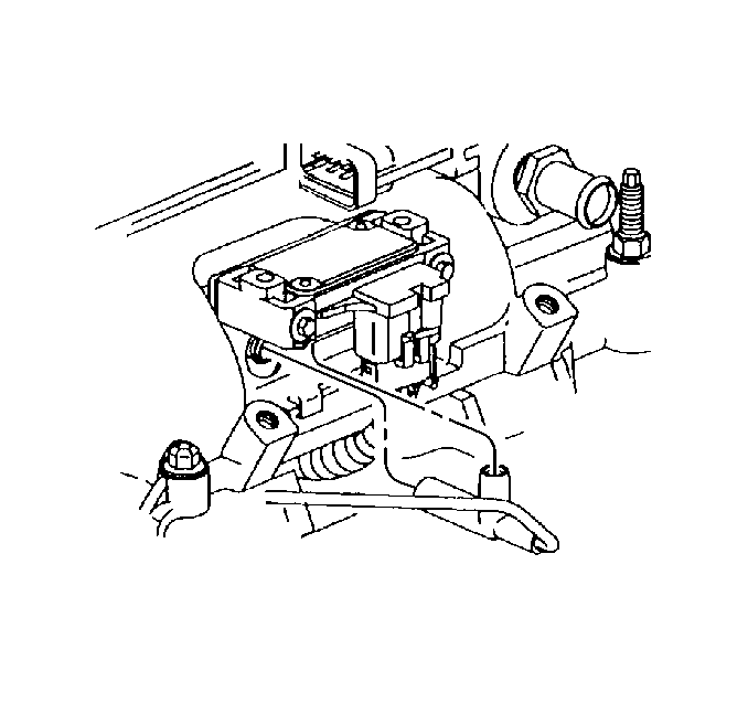
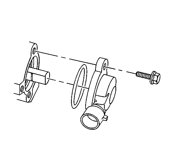
Knock Sensor (KS)
The knock sensor detects abnormal vibration (spark knocking) in the engine. The sensor is located on the engine block near the cylinders. The sensor produces an AC output voltage which increases with the severity of the knock. This signal voltage is input to the PCM. The PCM then adjusts the ignition control (IC) timing to reduce spark knock. DTC P0325 Knock Sensor (KS) Circuit and DTC P0327 Knock Sensor (KS) Circuit are designed to diagnose the PCM, the knock sensor, and related wiring, so problems encountered with the KS system should set a DTC.
Refer to Knock Sensor (KS) System Description description of the knock sensor system.
A/C Request Signal
This signal is transmitted two different ways depending on the content option, the first is communicated Class 2 from the HVAC controller to the PCM that an A/C mode is selected (CJ2). The second is a 12 volt signal from the HVAC controller to the PCM, the 12.0 volt signal indicates that an A/C mode is selected (CJ3, C60). The PCM uses this information to adjust the idle speed before turning on the A/C clutch. If this signal is not available to the PCM, the A/C compressor will be inoperative.
Refer to Powertrain Control Module Controlled Air Conditioning (A/C) Circuit Diagnosis for A/C clutch wiring diagrams and diagnosis of A/C clutch electrical system.
A/C Refrigerant Pressure Sensor
The A/C refrigerant pressure sensor signal indicates high side refrigerant pressure to the PCM. The PCM uses this information to adjust the idle air control (IAC) valve to compensate for the higher engine loads present with high A/C refrigerant pressures and to control the cooling fans. A fault in the A/C refrigerant pressure sensor signal will cause DTC P0530 Air Conditioning (A/C) Refrigerant Pressure Sensor Circuit to set.
Transaxle Controls
There are several switches and sensors located in the transaxle that are input or output to the PCM.
TCC Brake Switch
The torque converter clutch (TCC) brake switch signal to the PCM indicates when the brake pedal is applied. The TCC brake switch information is used by the PCM mainly to control the transaxle torque converter clutch.
Transaxle Range Switch
The transaxle range switch is part of the transaxle park/neutral position (PNP) switch mounted on the transaxle manual shaft. The 4 inputs from the transaxle range switch indicate to the PCM which position is selected by the transaxle selector lever. This information is used for transmission shift control, ignition timing, EVAP canister purge, EGR and IAC valve operation.
The combination of the four transaxle range input states determine the PCM commanded shift pattern. The input voltage level at the PCM is high (B+ battery positive voltage) when the transaxle range switch is open and low when the switch is closed to ground.
Transaxle Fluid Temperature (TFT) Sensor
The transaxle fluid temperature sensor is a thermistor which changes value based on the temperature of the transaxle fluid. A high transaxle fluid temperature may cause the vehicle to operate in hot mode. While in hot mode, shift points may be altered, 4th gear disabled, and TCC forced on in 2nd gear. A failure in the TFT sensor or associated wiring should cause DTC P0712 TFT Sensor Circuit Low Input or DTC P0713 TFT Sensor Circuit High Input to set. In this case, engine coolant temperature will be substituted for the TFT sensor value, and the transaxle will operate normally.
Vehicle Speed Sensor (VSS)
The vehicle speed sensor (VSS) sends a pulsing voltage signal to the PCM which the PCM converts to miles per hour. This sensor mainly controls the operation of the TCC, shift solenoids, and cruise control systems. There are several different types of vehicle speed sensors.
7X Crankshaft Position (CKP) Sensor
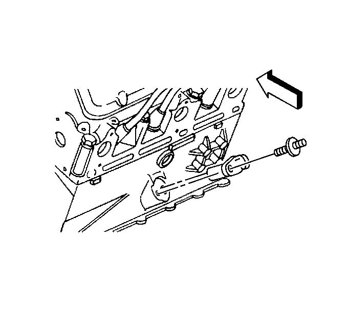
The 7X crankshaft position sensor provides a signal used by the ignition control module.
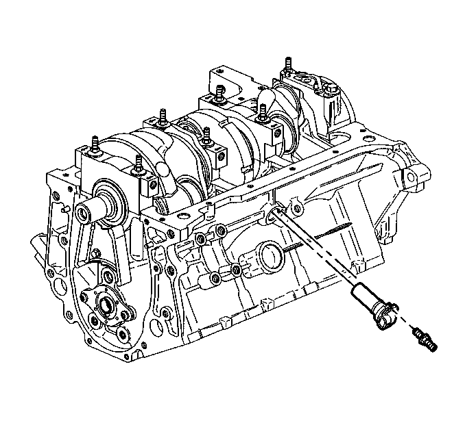
The ignition control module also uses the 7X crankshaft position sensor to generate 3X reference pulses which the PCM uses to calculate RPM and crankshaft position.
24X Crankshaft Position (CKP) Sensor
The 24X crankshaft position (CKP) sensor is used to improve idle spark control at engine speeds up to approximately 1600 RPM.
3X Reference
The PCM uses this signal, from the ignition control module to calculate engine speed and crankshaft position over 1600 RPM.
The PCM also uses the pulses on this circuit to initiate injector pulses. If the PCM receives no pulses on this circuit, DTC P1374 Crankshaft Position (CKP) High to Low Resolution Frequency Correlation will set and the PCM will use the 24X reference signal circuit for fuel and ignition control.
3X Reference Low
This is a ground circuit for the digital RPM counter inside the PCM, but the wire is connected to engine ground only through the ignition control module. Although this circuit is electrically connected to the PCM, it is not connected to ground at the PCM.
The PCM compares voltage pulses on the reference input circuits to pulses on this circuit, ignoring pulses that appear on both.
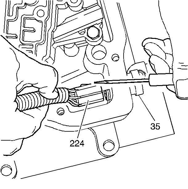
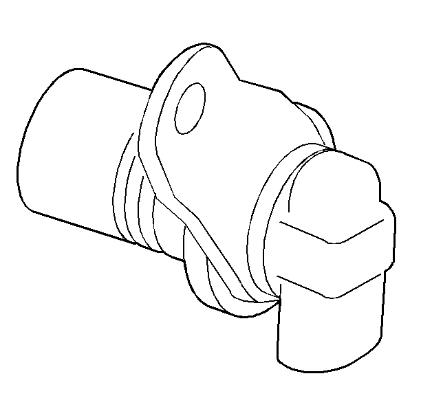
Camshaft Position (CMP) Sensor and CAM Signal
The camshaft position sensor sends a cam signal to the PCM which uses it as a sync pulse to trigger the injectors in proper sequence. The PCM uses the CAM signal to indicate the position of the #1 piston during its intake stroke. This allows the PCM to calculate true sequential fuel injection (SFI) mode of operation. If the PCM detects an incorrect CAM signal while the engine is running, DTC P0341 Camshaft Position (CMP) Sensor Performance will set.
If the CAM signal is lost while the engine is running, the fuel injection system will shift to a calculated sequential fuel injection mode based on the last fuel injection pulse, and the engine will continue to run. The engine can be restarted and will run in the calculated sequential mode as long as the fault is present with a 1 in 6 chance of injector sequence being correct.
Cruise Control Status Input
The cruise control module (CCM) sends the cruise status input to the PCM to indicate when cruise control is engaged.
The PCM monitors the cruise status signal while commanding cruise to be disengaged via the cruise inhibit circuit. Any of the following conditions may cause the PCM to inhibit cruise control operation:
| • | Engine not running long enough for cruise control operation. |
| • | Transaxle range inputs indicate park, neutral, low, or reverse gear selected. |
| • | Engine speed is too high or too low. |
| • | Vehicle speed is too high or too low. |
| • | ABS system is active for longer than 2 seconds. |
| • | Vehicle acceleration or deceleration rate is too high. |
Engine Oil Level Switch
The PCM monitors the engine oil level switch signal at start-up to determine if the engine oil is OK. If the PCM determines that a low oil level condition exists, the PCM will communicate the information over the Class 2 circuit to the IPC and it will illuminate the indicator lamp.
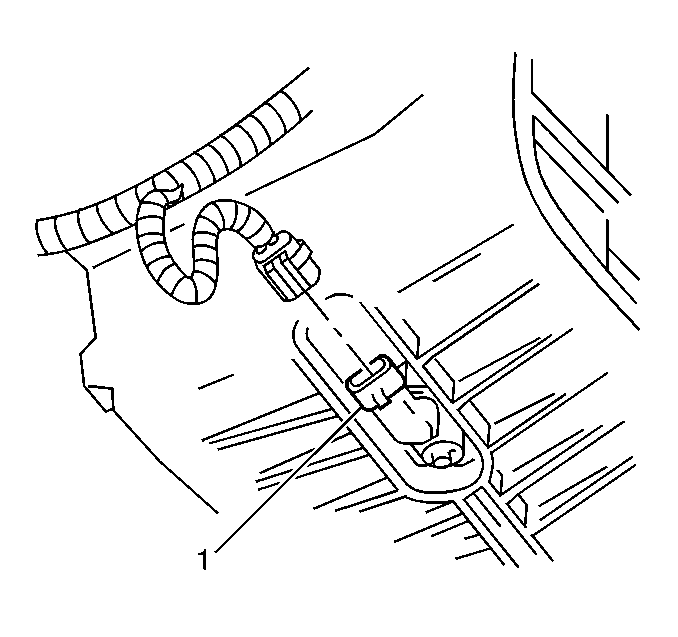
Engine Oil Pressure Switch
The PCM monitors the engine oil pressure switch (1) signal to determine if the engine oil pressure is OK. If the PCM determines that a low oil pressure condition exists, the PCM will communicate the information over the Class 2 circuit to the IPC and it will illuminate the indicator lamp.