Fuel Injector Replacement VIN K
Removal Procedure
Tools Required
J 34730 Fuel Pressure Gauge
Notice: Use care in removing the fuel injectors in order to prevent damage to the fuel injector electrical connector pins or the fuel injector nozzles. Do not immerse the fuel injector in any type of cleaner. The fuel injector is an electrical component and may be damaged by this cleaning method.
Important: The fuel injector is serviced as a complete assembly only. If the fuel injectors are found to be leaking, the engine oil may be contaminated with fuel.
- Relieve the fuel pressure. Refer to Fuel Pressure Relief .
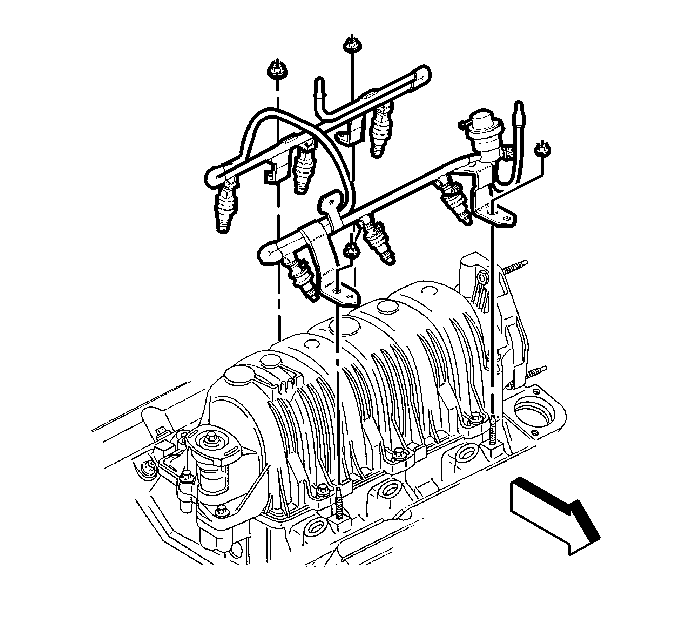
- Remove the fuel rail. Refer to Fuel Injection Fuel Rail Assembly Replacement .
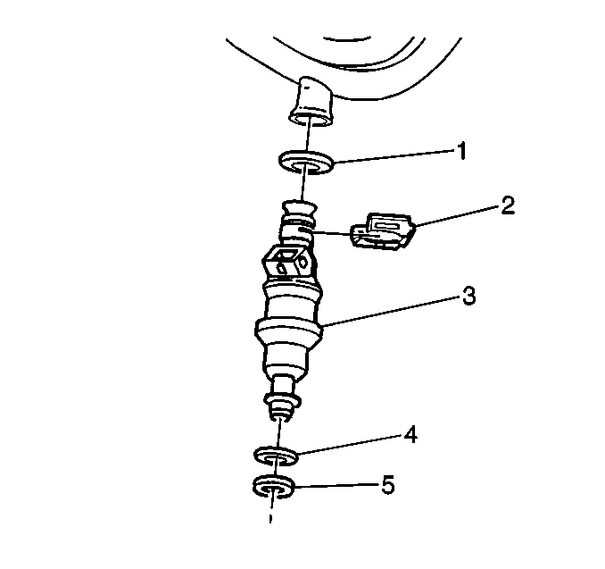
- Remove the fuel injector retaining clips (2).
- Remove the fuel injectors (3).
- Remove the fuel injector upper O-ring (1).
- Remove the fuel injector lower O-ring (5).
- Remove the O-ring backup (4).


Important: Fuel injector O-rings should always be replaced whenever fuel injectors are serviced.
Each fuel injector is calibrated for a specific flow rate. Be sure to use the correct part number when ordering replacement fuel injectors. The fuel injector lower O-ring (5) uses a nylon collar, called the O-ring backup (4), to properly position the O-ring on the fuel injector. Be sure to reinstall the O-ring backup, or the sealing O-ring may move on the fuel injector when installing the fuel rail. If the sealing O-ring is not seated properly, a vacuum leak is possible and driveability complaints may occur.Installation Procedure
- Coat all new O-rings with engine oil before installing
- Install the fuel injector back up O-ring (4).
- Install the fuel injector lower O-ring (5).
- Install the fuel injector upper O-ring (1).
- Install the fuel injector to the fuel rail (3).
- Install the fuel injector retaining clips (2).
- Install the fuel rail. Refer to Fuel Injection Fuel Rail Assembly Replacement .
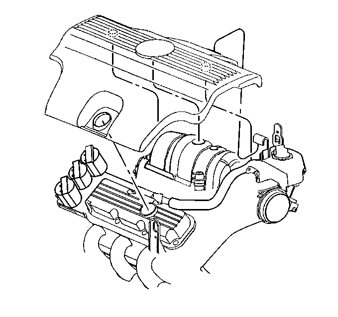
- Install the fuel injector sight shield. Refer to Fuel Injector Sight Shield Replacement .
Important: When ordering new fuel injectors, be sure to order the correct injector for the application being serviced.
The upper and lower fuel injector O-rings use different part numbers. To identify the correct O-ring, the upper O-ring is black and the lower O-ring is brown. Both O-rings are the same size but consist of different material. The fuel injector lower O-ring uses a nylon collar, called the O-ring backup, to properly position the O-ring on the injector. Always reinstall the O-ring backup, or the sealing O-ring may move on the injector when installing the fuel rail and result in a possible vacuum leak. Fuel injector O-rings should always be replaced whenever fuel injectors are serviced.


Fuel Injector Replacement VIN 1
Removal Procedure
Tools Required
| • | J 34730 Fuel Pressure Gauge |
| • | J 37088-A Fuel line Quick-Connect Tools |
Notice: Use care in removing the fuel injectors in order to prevent damage to the fuel injector electrical connector pins or the fuel injector nozzles. Do not immerse the fuel injector in any type of cleaner. The fuel injector is an electrical component and may be damaged by this cleaning method.
Important: The fuel injector is serviced as a complete assembly only. If the fuel injectors are found to be leaking, the engine oil may be contaminated with fuel.
- Relieve the fuel system pressure. Refer to Fuel Pressure Relief .
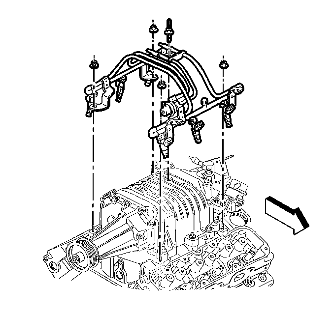
- Remove the fuel rail. Refer to Fuel Injection Fuel Rail Assembly Replacement .
- Remove the fuel injector retaining clips (2).
- Remove the fuel injectors (3).
- Remove the fuel injector upper O-ring (1).
- Remove the fuel injector lower O-ring (5).
- Remove the O-ring backup (4).


Important: Fuel injector O-rings should always be replaced whenever fuel injectors are serviced.
Each fuel injector is calibrated for a specific flow rate. Be sure to use the correct part number when ordering replacement fuel injectors. The fuel injector lower O-ring (5) uses a nylon collar, called the O-ring backup (4), to properly position the O-ring on the fuel injector. Be sure to reinstall the O-ring backup, or the sealing O-ring may move on the fuel injector when installing the fuel rail. If the sealing O-ring is not seated properly, a vacuum leak is possible and driveability complaints may occur.Installation Procedure
- Coat all new O-rings with engine oil before installing
- Install the fuel injector back up O-ring (4).
- Install the fuel injector lower O-ring (5).
- Install the fuel injector upper O-ring (1).
- Install the fuel injector to the fuel rail (3).
- Install the fuel injector retaining clips (2).
- Install the fuel rail. Refer to Fuel Injection Fuel Rail Assembly Replacement .
- Install the fuel injector sight shield. Refer to Fuel Injector Sight Shield Replacement .
Important: When ordering new fuel injectors, be sure to order the correct injector for the application being serviced.
The upper and lower fuel injector O-rings use different part numbers. To identify the correct O-ring, the upper O-ring is black and the lower O-ring is brown. Both O-rings are the same size but consist of different material. The fuel injector lower O-ring uses a nylon collar, called the O-ring backup, to properly position the O-ring on the injector. Always reinstall the O-ring backup, or the sealing O-ring may move on the injector when installing the fuel rail and result in a possible vacuum leak. Fuel injector O-rings should always be replaced whenever fuel injectors are serviced.

Notice: Use the correct fastener in the correct location. Replacement fasteners must be the correct part number for that application. Fasteners requiring replacement or fasteners requiring the use of thread locking compound or sealant are identified in the service procedure. Do not use paints, lubricants, or corrosion inhibitors on fasteners or fastener joint surfaces unless specified. These coatings affect fastener torque and joint clamping force and may damage the fastener. Use the correct tightening sequence and specifications when installing fasteners in order to avoid damage to parts and systems.
Tighten
Tighten the nut to 2 N·m (18 lb in).
