Removal Procedure
- Remove the valve rocker arm covers. Refer to Valve Rocker Arm Cover Replacement .
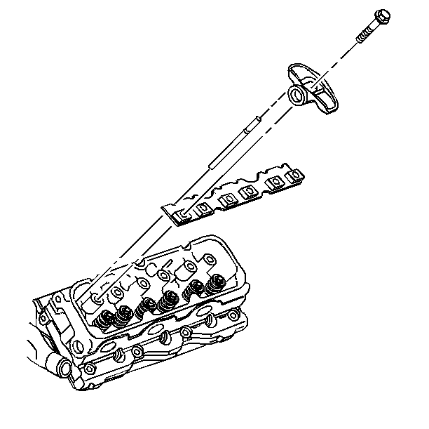
- Remove the valve rocker arm pedestal retaining bolts.
- Remove the pedestal.
- Remove the rocker arm assembly.
- Remove the pushrods.
- Clean the valve rocker arms, pushrods and pedestal bolts in a suitable solution.
- Inspect the valve rocker arms, pushrods and pedestal bolts for wear.
- Clean the bolts of all thread adhesive.
Important:
• Place the assemblies on a clean surface. • Store the components in order. Reassemble the components in the
same location and with the same mating surfaces as when removed.
Installation Procedure
Tools Required
J 36660-A Torque Angle Meter
- Install the pushrods.
- Install the valve rocker arm assembly.
- Install the pedestal.
- Apply GM P/N 12345493 threadlocker compound or equivalent to the valve rocker arm bolt threads.
- Install the valve rocker arm pedestal retaining bolts.
- Install the valve rocker arm covers. Refer to Valve Rocker Arm Cover Replacement .
- Listen for valve train noise.
Notice: The two bolts which fasten the lower intake manifold to the cylinder head are accessible only after the upper intake is removed. The bolts are located in the right front and left rear corners of the lower intake manifold. Remove the upper intake manifold to service the lower intake.
Notice: Use the correct fastener in the correct location. Replacement fasteners must be the correct part number for that application. Fasteners requiring replacement or fasteners requiring the use of thread locking compound or sealant are identified in the service procedure. Do not use paints, lubricants, or corrosion inhibitors on fasteners or fastener joint surfaces unless specified. These coatings affect fastener torque and joint clamping force and may damage the fastener. Use the correct tightening sequence and specifications when installing fasteners in order to avoid damage to parts and systems.
Tighten
Tighten the valve rocker arm bolts to 15 N·m (11 lb ft) +90 degrees
using J 36660-A
.
