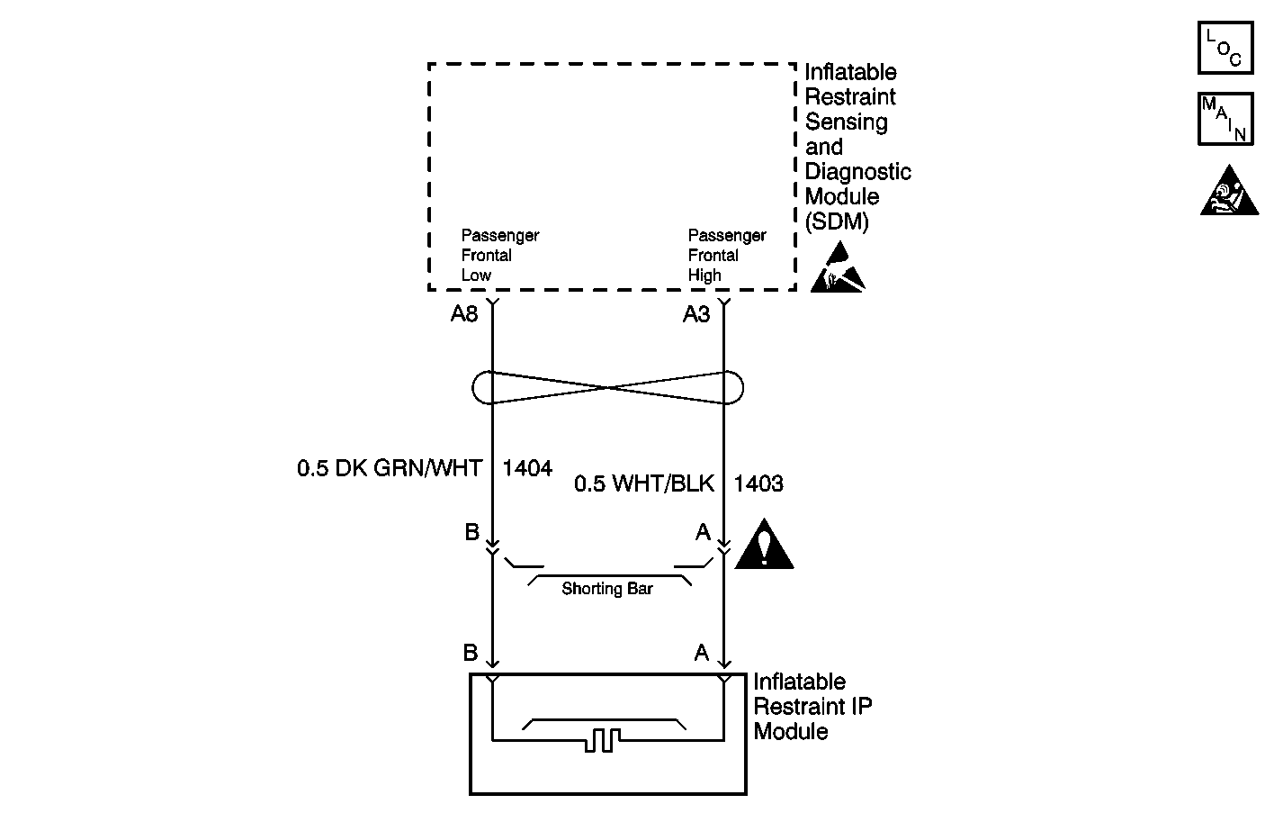
Circuit Description
When you first turn ON the ignition, the inflatable restraint sensing and diagnostic module (SDM) performs tests to diagnose critical malfunctions within itself. Then the SDM performs the following continuous diagnostic tests on the deployment loops:
| • | Deployment loop voltage out of range test |
| • | Deployment loop resistance measurement test |
If the voltage out of range test detects a short to voltage condition, the resistance measurement test for that deployment loop will not be performed.
Conditions for Running the DTC
| • | Ignition 1 voltage is within the normal operating voltage range. |
| • | Passenger frontal deployment loop is not open. |
| • | Passenger frontal deployment loop is not shorted to voltage. |
| • | Passenger frontal deployment loop is not shorted to ground. |
Conditions for Setting the DTC
Passenger frontal deployment loop resistance is less than 1.3 ohms for 500 milliseconds.
Action Taken When the DTC Sets
The SDM commands ON the AIR BAG warning lamp via Class 2 serial data.
Conditions for Clearing the DTC
| • | The resistance of the passenger frontal deployment loop is at least 1.3 ohms or more for 500 milliseconds. |
| • | You can issue a CLEAR CODES command. |
| • | A history DTC will clear once 255 malfunction free ignition cycles have occurred. |
Diagnostic Aids
The following can cause an intermittent condition:
| • | A short between the passenger frontal high and the passenger frontal low circuits |
| • | A malfunctioning shorting bar on the inflatable restraint IP module 2-way connector |
| Refer to Testing for Intermittent Conditions and Poor Connections in Wiring Systems. |
Test Description
The number(s) below refer to the step number(s) on the diagnostic table.
-
This step checks the IP/passenger inflator module in-line connector for physical damage.
-
This step checks to see if there is a malfunctioning inflatable restraint passenger inflator module.
-
This step determines if there is a short between passenger frontal high and low deployment circuits or if there is a malfunctioning SDM.
Step | Action | Value(s) | Yes | No | ||||||||
|---|---|---|---|---|---|---|---|---|---|---|---|---|
1 | Did you perform the A Diagnostic System Check? | -- | Go to Step 2 | |||||||||
Does connector exhibits any signs of corrosion, terminal damaged, or poor connections? | -- | Go to Step 3 | Go to Step 4 | |||||||||
3 | Replace the wiring harness side of in-line connector. Refer to Connector Repairs in Wiring Systems. Did you complete the replacement? | -- | Go to Step 10 | -- | ||||||||
4 |
Does the scan tool indicate that this DTC is current? | -- | Go to Step 5 | Go to Diagnostic Aids | ||||||||
Does the scan tool indicate that this DTC is current? | -- | Go to Step 7 | Go to Step 6 | |||||||||
6 |
Did you complete the replacement? | -- | Go to Step 10 | -- | ||||||||
Does the resistance measure less than the specified value? | OL | Go to Step 8 | Go to Step 9 | |||||||||
8 | Locate and repair the short between high and low deployment circuits. Refer to Circuit Testing and Wiring Repairs in Wiring Systems. Did you complete the repair? | -- | Go to Step 10 | -- | ||||||||
9 | Replace the SDM. Refer to Inflatable Restraint Sensing and Diagnostic Module Replacement . Did you complete the replacement? | -- | Go to Step 10 | -- | ||||||||
10 |
Did you complete the action? | -- | -- |
