For 1990-2009 cars only
Exhaust Manifold Installation - Left Side W/O RPO NC1 or NF7
- If the engine is equipped with coolant heaters, install the left side (1) heater as follows:
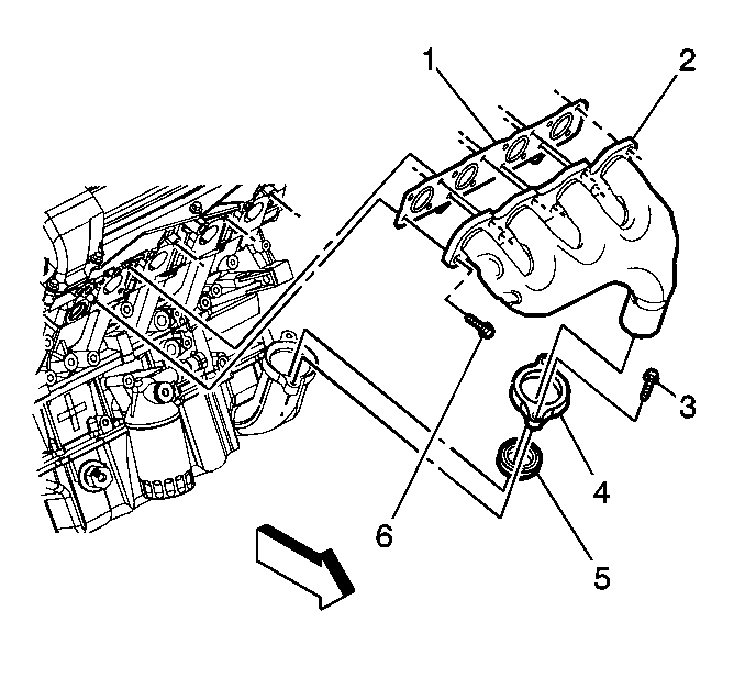
- With the manifold still on the bench, position a new manifold gasket (1) in place on the manifold sealing surface.
- Install 2 outer manifold bolts (6) in the manifold to retain the gasket.
- Install a new manifold to intermediate pipe flange gasket (5).
- Using 2 hands, place the manifold (2) in the intermediate pipe and onto the cylinder head.
- Install new manifold flange bolts (3) for maximum joint integrity. Hand tighten. Do not torque the flange bolts to specification until the engine is mounted in the vehicle.
- Hand tighten the 2 outer manifold bolts.
- Install the remaining manifold bolts. Tighten the exhaust manifold bolts (6) to 25 N·m (18 lb ft).
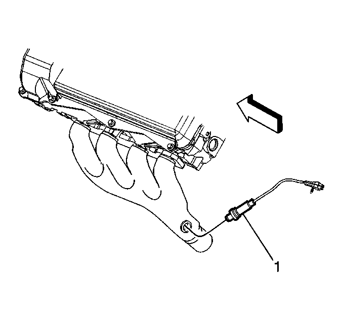
- Coat the oxygen sensor threads with high temperature anti-seize, GM P/N 12377953 or equivalent.
- Install the oxygen sensor (1) and tighten to 40 N·m (30 lb ft).
Caution: Refer to Fastener Caution in the Preface section.
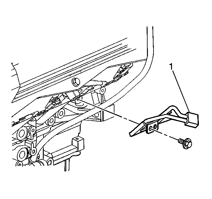
| 1.1. | Place the coolant heater (1) in position on the cylinder block. |
| 1.2. | Install the coolant heater bolt and tighten to 10 N·m (89 lb in). |
Exhaust Manifold Installation - Left Side With RPO NC1 or NF7
- If the engine is equipped with coolant heaters, install the left side (1) heater as follows:
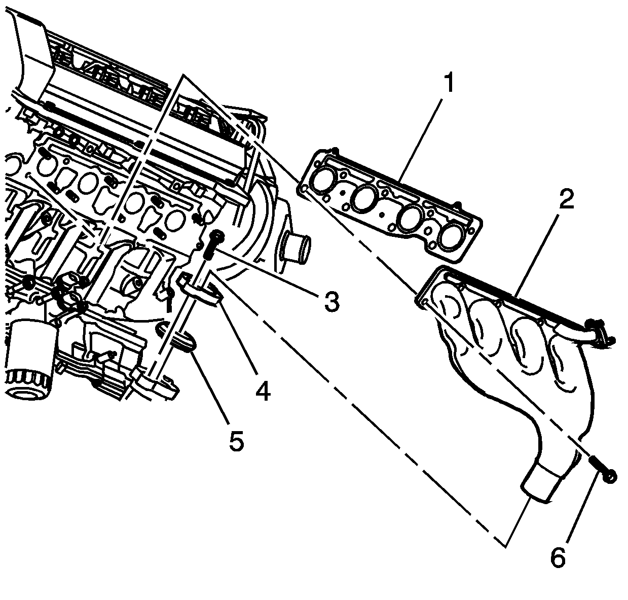
- With the manifold still on the bench, position a new manifold gasket (1) in place on the manifold sealing surface.
- Install 2 outer manifold bolts (6) in the manifold to retain the gasket.
- Install a new manifold to intermediate pipe flange gasket (5).
- Using 2 hands, place the manifold (2) in the intermediate pipe and onto the cylinder head.
- Install new manifold flange bolts (3) for maximum joint integrity. Hand tighten. Do not torque the flange bolts to specification until the engine is mounted in the vehicle.
- Hand tighten the 2 outer manifold bolts.
- Install the remaining manifold bolts and tighten to 25 N·m (18 lb ft).
- Coat the oxygen sensor threads with high temperature anti-seize, GM P/N 12377953 or equivalent.
- Install the oxygen sensor (1) and tighten to 40 N·m (30 lb ft).
- Install the NEW AIR valve pipe gasket.
- Install the AIR valve.
- Install the AIR valve nuts to the mounting bracket and tighten to 9 N·m (80 lb in).
- Install the AIR valve bolt through the mounting bracket and tighten to 9 N·m (80 lb in).
- Install the AIR valve pipe nuts to the exhaust manifold and tighten to 9 N·m (80 lb in).
Caution: Refer to Fastener Caution in the Preface section.

| 1.1. | Place the coolant heater (1) in position on the cylinder block. |
| 1.2. | Install the coolant heater bolt and tighten to 10 N·m (89 lb in). |
Note: DO NOT reuse the exhaust manifold gasket.

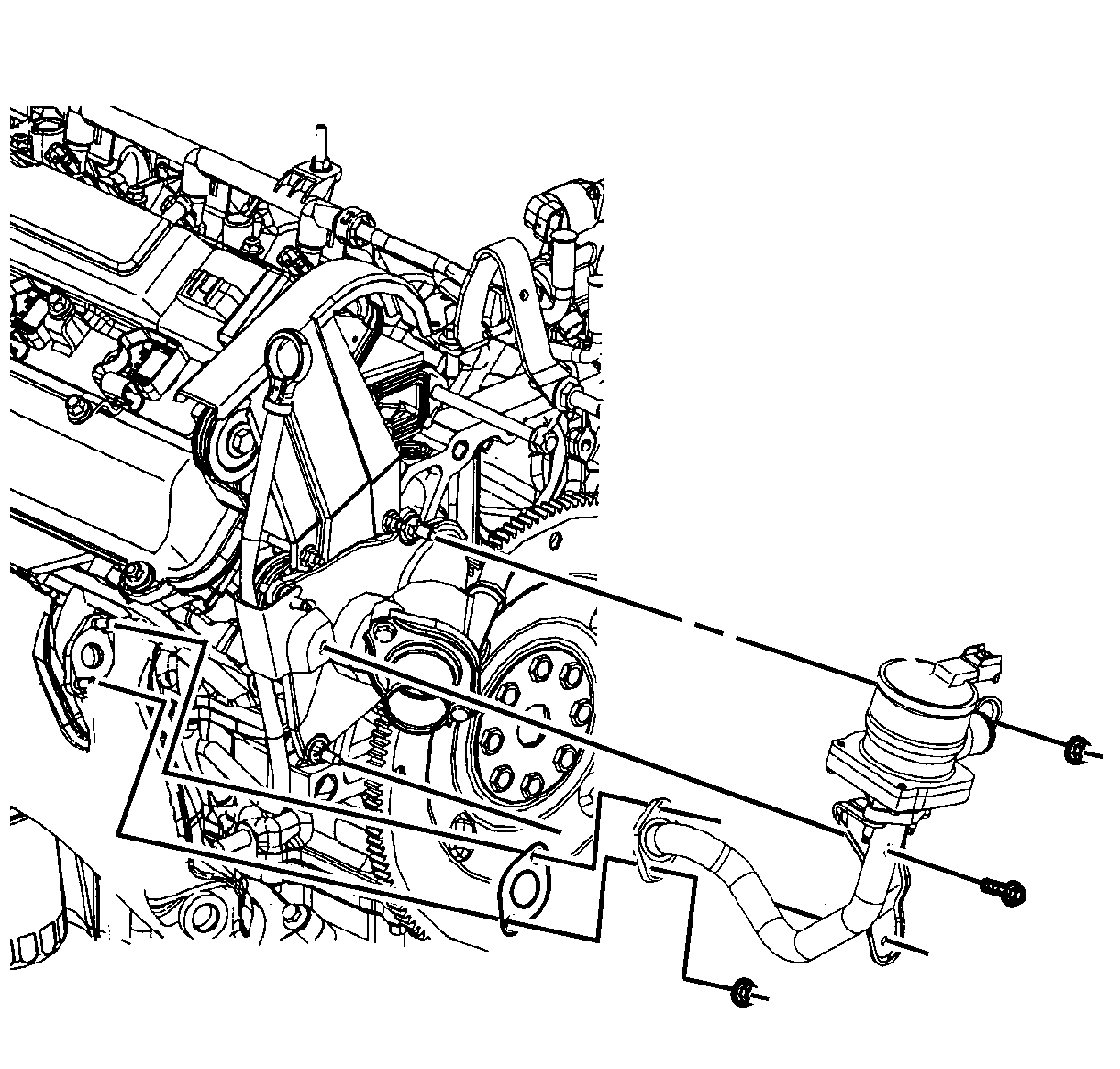
Note: DO NOT reuse the old secondary air injection (AIR) valve pipe gasket.
